A contactor is an electrically controlled switch used to turn electrical power circuits on and off. It is commonly used in industrial and commercial applications to control high-power loads.
Unlike ordinary switches, contactors are designed for frequent switching operations and can handle large electrical loads such as motors, heaters, lighting systems, and industrial machinery.
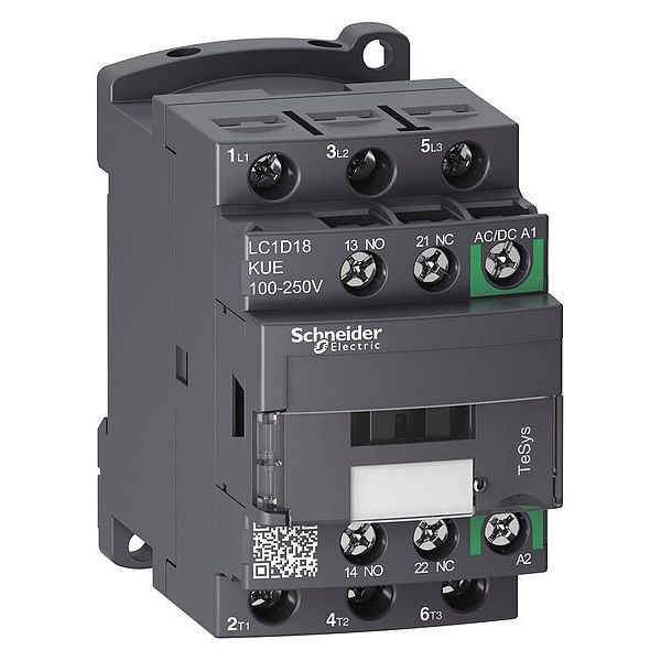
Construction of Contactor
- Electromagnetic Coil
Wound around an iron core. When energised, creates a magnetic field that pulls the armature. Available in AC or DC variants coil voltage is your selection parameter.
- Iron Core (Stator)
Fixed E or U-shaped laminated core. Lamination reduces eddy current losses in AC contactors. Forms the stationary half of the magnetic circuit.
- Armature (Plunger)
The moving magnetic part. Attracted to the core when coil energises. Its mechanical movement opens or closes the main contacts.
- Main Contacts
Heavy-duty silver alloy (AgCdO or AgSnO₂) contacts that carry load current. Typically 3-pole for 3-phase motors. Designed for frequent switching.
- Auxiliary Contacts
Low-current contacts (NO/NC) used for control circuit interlocking, indicator lamps, and PLC feedback signals.
- Return Spring
Pulls armature back when coil de-energises, opening the main contacts. Spring force determines dropout voltage behaviour.
- Arc Extinction Chamber
Metal arc splitter plates that divide, cool, and extinguish the arc formed when contacts open under load. Critical for contact longevity.
- Housing / Enclosure
Thermoplastic or thermoset body. Provides electrical isolation, mechanical protection, and panel mounting interface (DIN rail or screw-mount).
Material note: Silver cadmium oxide (AgCdO) was the gold standard for contacts for decades. Due to cadmium toxicity and RoHS regulations, silver tin oxide (AgSnO₂) is now the modern alternative slightly different arc-handling characteristics, but compliant and reliable.
How a contactor actually works
The operating principle is elegantly based on electromagnetic induction. Here’s the step-by-step sequence of what happens when you energise a contactor:
- Control signal applied to coil terminals
A control voltage (e.g., 24V DC, 110V AC, or 230V AC depending on coil rating) is applied across the coil terminals A1 and A2. This is typically from a PLC output, push-button, or relay.
2. Electromagnetic field is established
Current flows through the coil windings, generating a magnetic flux in the iron core (stator). The flux builds up in milliseconds this is where the characteristic “clunk” sound originates from.
3. Armature is attracted to the core
The magnetic force exceeds the spring’s restoring force. The moveable armature (and the contact bridge attached to it) is pulled toward the fixed core. Pickup voltage is typically 85–110% of rated coil voltage.
4. Main contacts close
Contact bridges make contact with the stationary contacts. The main power circuit is now closed the load (motor, heater, lighting bank) receives supply. Contact bounce is dampened by contact spring pressure.
5. Auxiliary contacts change state
Simultaneously, NO auxiliary contacts close and NC contacts open. These feed back to the control circuit enabling self-holding (latching) logic, interlocking other devices, or signalling a PLC.
6. Coil de-energised contacts open
When coil voltage is removed (or drops below dropout voltage, typically 20–75% of rated), the magnetic field collapses. The return spring drives the armature back, opening the main contacts. An arc is drawn and extinguished in the arc chamber.
Shading ring detail (AC contactors): AC contactors include a copper shading ring on the pole face of the stator. Since AC flux passes through zero twice per cycle, the magnetic force would also drop to zero, causing the armature to chatter. The shading ring creates a phase-shifted flux component, ensuring the total magnetic force never reaches zero eliminating the chatter and the buzzing noise.
Types of contactors
Not all contactors are built the same selection depends on your load type, voltage, switching frequency, and application. Here’s a breakdown of the main categories:
- AC Contactor
Most common type. Used for AC motor control, lighting, and HVAC. Features shading rings and laminated cores. IEC AC-3 duty class for squirrel-cage motor switching.
- DC Contactor
Designed for DC circuits where arc extinction is harder (no natural zero-crossing). Uses magnetic blowout coils or double-break contacts. Common in traction, battery systems, and EVs.
- Vacuum Contactor
Contacts sealed inside a vacuum bottle. Arcs extinguish rapidly due to lack of ionisable gas. Used in medium-voltage (3.3kV–11kV) applications mining, utilities, substations.
- Reversing Contactor
Two contactors interlocked mechanically and electrically. Swapping two phases reverses motor rotation direction. Used in cranes, lifts, conveyor reversals. Interlocking prevents simultaneous closure.
- Star-Delta Contactor
Three contactors (main, star, delta) working in sequence to soft-start large motors. Reduces starting current to 1/3 of DOL value. Timed transition from star to delta connection.
- Solid State Contactor
No moving parts uses SCR/TRIAC or IGBT pairs for switching. Silent operation, extremely high switching frequency, zero mechanical wear. Used in heating control and high-cycle applications.
Applications of Contactor
- Motor Control Centres (MCCs)
- HVAC Systems
- Lighting Control
- EV Charging & Battery Systems
- Crane & Hoist Control
Contactor vs. relay vs. circuit breaker
The most common source of confusion for students and junior engineers. Here’s the practical distinction:
| Parameter | Contactor | Relay | Circuit Breaker |
|---|---|---|---|
| Current rating | 9A to 630A+ | Up to ~16A | Up to thousands of A |
| Primary function | Switching/control | Switching/control | Overcurrent protection |
| Fault interruption | No | No | Yes (designed for it) |
| Switching frequency | High (industrial) | High (control) | Low (rare operation) |
| Manual reset needed? | No | No | Yes (after trip) |
| Typical location | Motor control panel | Control circuit | Distribution board |
| Contact material | Heavy silver alloy | Light silver/gold | Copper/silver alloy |