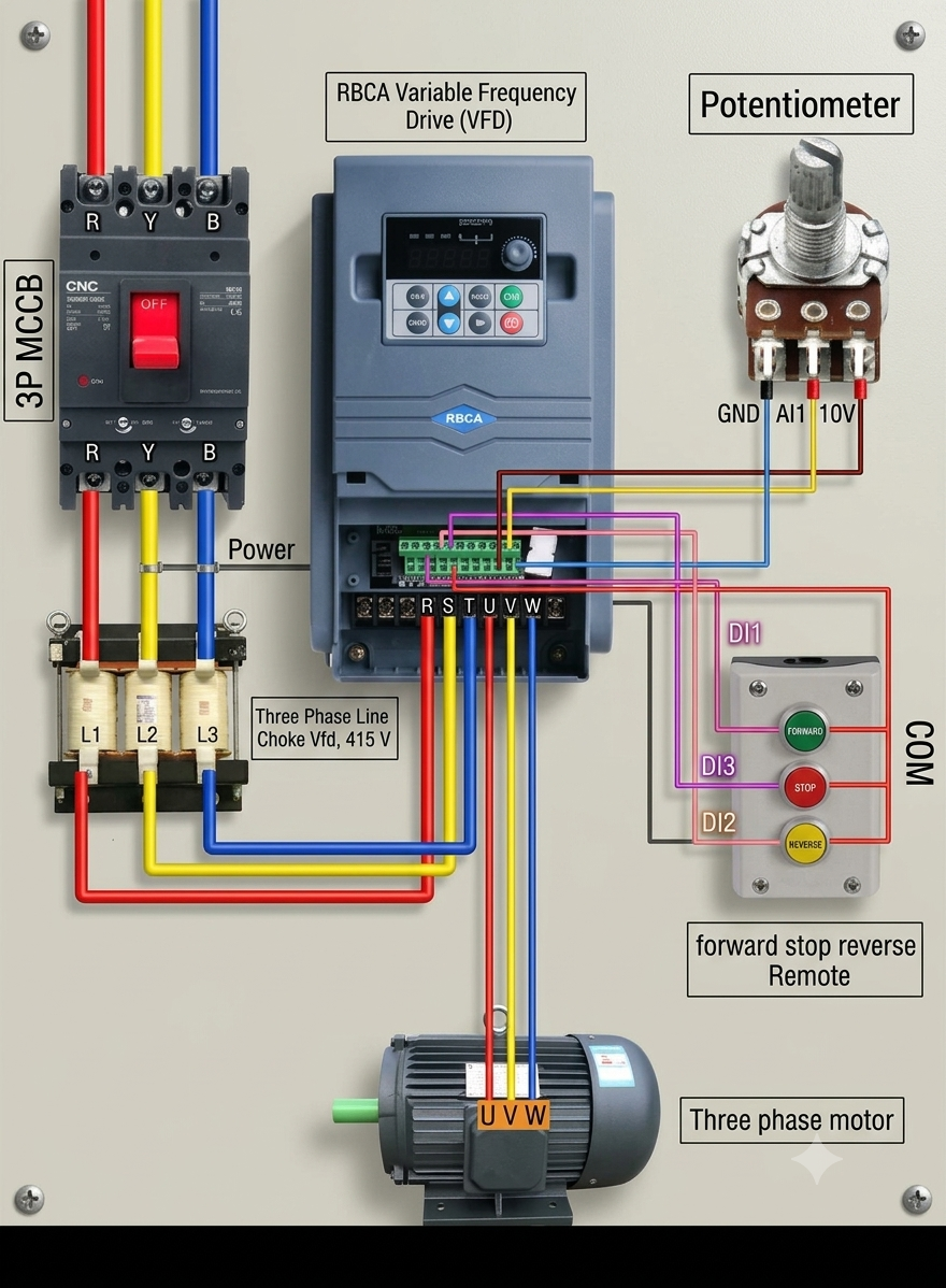
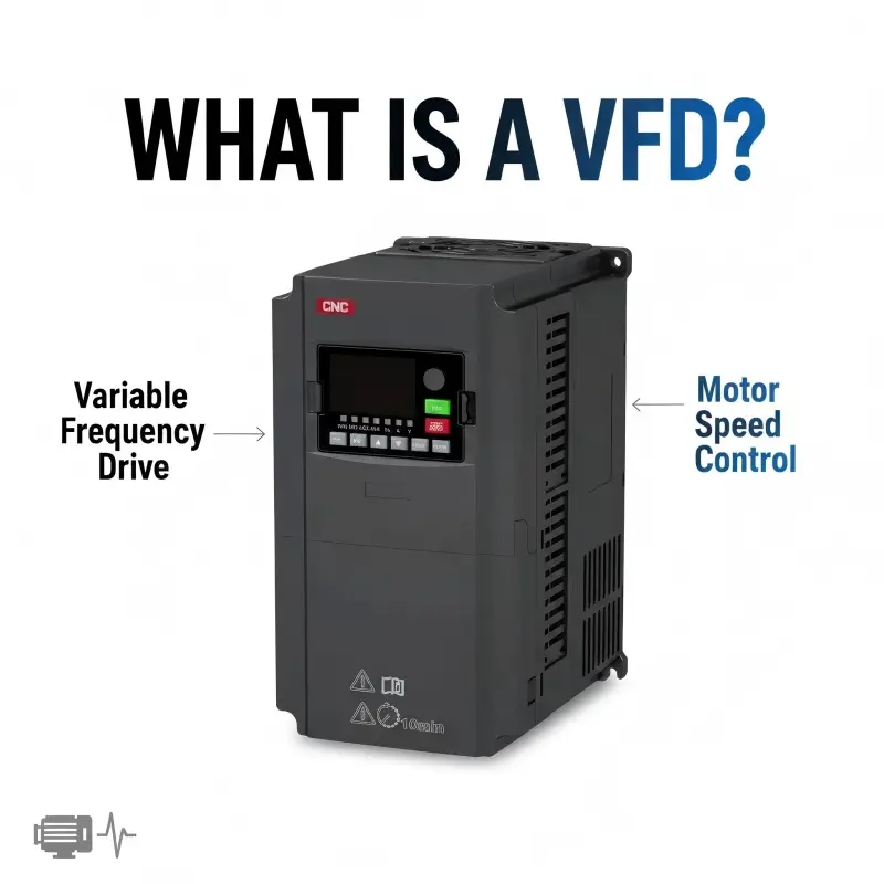
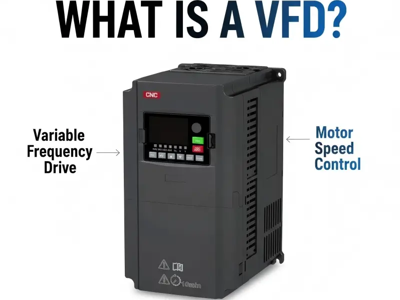
A Variable Frequency Drive, commonly known as a VFD, is an electronic device used to control the speed and torque of an electric motor by varying the input frequency and voltage.
Put simply, instead of running a motor at full speed all the time, variable frequency drives allow operators to regulate motor behaviour based on actual demand.
This capability is critical for:
- Energy optimisation
- Process control
- Equipment protection
- Smooth motor operation
A VFD transforms fixed-speed motors into adjustable-speed systems.
Working Principle
A simplified VFD working principle diagram is shown in below. The three major sections of the controller are as follows:
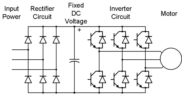
The two main features of variable frequency drive are adjustable speeds and soft start/stop capabilities. These two features make VFD’s a powerful controller to control the AC motors. VFD consists of mainly four sections; those are rectifier, intermediate DC link, inverter, and controlling circuit.
Rectifier:
It is the first stage of a variable frequency drive. It converts AC power fed from mains to DC power. This section can be unidirectional or bidirectional based on the application used like the four-quadrant operation of the motor. It utilizes diodes, SCR’s, transistors, and other electronic switching devices.
If it uses diodes, converted DC power is uncontrolled output while using SCR, DC output power is varied by gate control. A minimum of six diodes are required for the three-phase conversion, so the rectifier unit is considered as six pulse converter.
DC bus:
DC power from the rectifier section is fed to the DC link. This section consists of capacitors and inductors to smooth against ripples and store the DC power. The main function of the DC link is to receive, store and deliver DC power.
Inverter:
This section comprises of electronic switches like transistors, thyristors, IGBT, etc. It receives DC power from DC link and converts into AC which is delivered to the motor. It uses modulation techniques like pulse width modulation to vary output frequency for controlling the speed of induction motor.
Control circuit:
It consists of a microprocessor unit and performs various functions like controlling, configuring drive settings, fault conditions, and interfacing communication protocols. It receives a feedback signal from the motor as current speed reference and accordingly regulates the ratio of voltage to frequency to control motor speed.
Variable Frequency Drives (VFDs) are electronic devices used to control AC motor speed and torque by adjusting the input voltage and frequency. They are primarily classified into three main categories based on their power conversion method, along with various control and load configurations.
Types of VFD
1. Classification by Power Conversion
- Voltage Source Inverter (VSI): The most common and widely used drive. It converts AC to DC, filters it with a capacitor bank, and then inverts it back to AC. It is highly reliable and ideal for general-purpose applications.
- Current Source Inverter (CSI): An older, legacy topology. It converts AC to DC using large inductors and delivers a clean current waveform. It is mainly used for high-power, specialized applications but struggles with low-speed stability.
- Pulse Width Modulation (PWM): An advanced VSI modification. It utilizes rapid switching of transistors to pulse voltage to the motor in varying widths, closely mimicking a sine wave. It provides high efficiency and excellent motor control.
2. Classification by Control Method
- Scalar Control (V/Hz): Maintains a constant ratio between voltage and frequency. It is simple and cost-effective, best used for basic applications like fans and centrifugal pumps where extreme precision isn’t required.
- Vector Control (Field-Oriented Control): Separates the motor current into torque-producing and flux-producing components. This allows for highly precise speed and torque regulation, making it ideal for conveyors and extruders.
- Direct Torque Control (DTC): An advanced control method that directly calculates and adjusts motor flux and torque in real-time without the need for traditional modulation. It provides extremely fast, high-accuracy responses for dynamic industrial systems.
3. Classification by Load Types
- Variable Torque: Typically found in centrifugal fans and pumps. The torque required increases with the square of the speed, offering massive energy-saving potential by simply slowing the motor down.
- Constant Torque: Typical of heavy machinery like conveyors, extruders, and positive-displacement pumps. These require the same amount of torque to operate regardless of the motor speed.
- Constant Power: Found in applications like winders and lathes, where the load requires high torque at low speeds and low torque at high speeds to maintain a constant horsepower.
Advantages of VFDs
- Energy Savings: VFDs adjust motor speed to precisely match the load requirement. This is highly effective for centrifugal fans and pumps, where reducing speed by half can cut power consumption by up to $87\%$.
- Reduced Mechanical Stress: By enabling “soft” starts and stops, VFDs eliminate the high inrush currents and mechanical shocks associated with direct-on-line (DOL) starting. This prolongs the life of belts, gears, and motors.
- Precise Process Control: Operators can fine-tune system performance to maintain steady flow rates, pressure, or temperature without relying on restrictive throttling valves or dampers.
- Optimized Power Factor: Modern VFDs improve the power factor of the system, reducing the reactive power drawn from the electrical grid.
- Built-in Protections: VFDs offer advanced fault protection against phase loss, overvoltage, undervoltage, and motor overloads.
Disadvantages of VFDs
- High Initial Investment: While VFDs pay for themselves over time, the upfront purchase and installation costs are significantly higher than standard motor starters.
- Harmonic Distortion: The process of converting AC to DC and back to AC can introduce electrical noise (harmonics) back into the supply grid, potentially interfering with other sensitive equipment and requiring additional harmonic filters.
- Increased Complexity: VFDs require careful configuration and parameter tuning. Their setup generally requires a steeper learning curve compared to simple across-the-line starters.
- Environmental Sensitivity: Standard VFDs are sensitive to extreme temperatures, dust, and moisture. They often require climate-controlled rooms or specialized NEMA enclosures.
- Motor Heating at Low Speeds: When standard motors operate at very low speeds, their internal cooling fans (which are usually attached to the motor shaft) also slow down. This can lead to overheating unless forced-ventilation cooling is added.
Key Uses & Applications
- HVAC Systems
- Water Treatment
- Manufacturing & Conveyors
- Refrigeration & Compressors