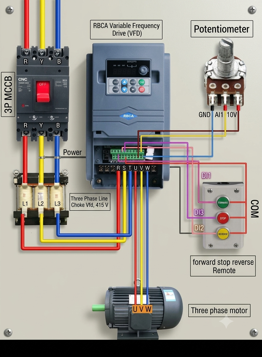
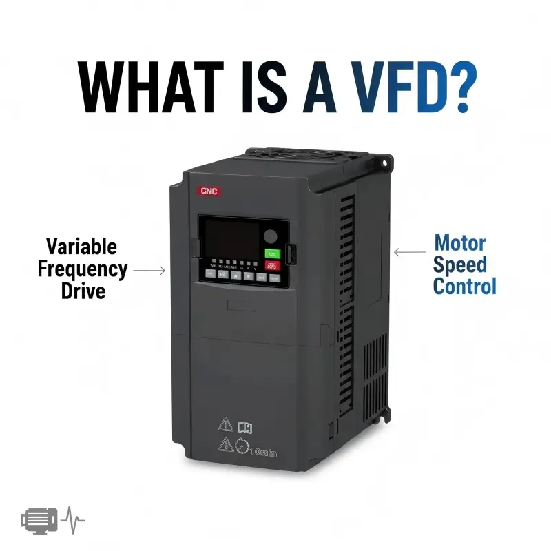
A Variable Frequency Drive (VFD) is used to control the speed, direction, and torque of a 3-phase motor. Below is a simple explanation of each part in the wiring diagram to help anyone learning automation or industrial maintenance.
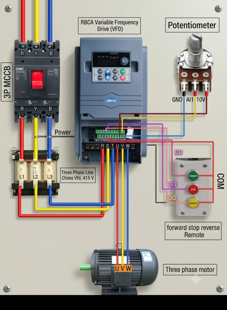
1. Power Supply (R, S, T → Input)
The VFD receives 3-phase AC supply from the main breaker.
The terminals R, S, T are connected to the 380V/415V input.
This energizes the VFD so it can run and control the motor.
🔹 Simply: R–S–T = Power into the VFD
2. Potentiometer (Manual Speed Control)
A 10kΩ potentiometer is connected to the VFD’s analog input terminals.
It controls the frequency (Hz) of the drive.
Turning the knob increases or decreases motor speed smoothly.
🔹 Use: Manual speed control when no PLC/HMI is used
3. Control Buttons (Forward / Stop / Reverse)
Push buttons are wired to the VFD’s digital input terminals.
Forward (Green): Runs the motor in forward rotation
Reverse (Red): Runs the motor in reverse rotation
Stop: Safely stops the motor immediately
🔹 These make start/stop and direction control simple and safe
4. Alarm/Warning Indicator
A signal lamp is connected to the VFD’s relay output.
It turns ON whenever the VFD detects a fault such as: overload, overheat, undervoltage, wiring error, etc
🔹 Helps with quick troubleshooting and safety
5. Motor Output (U, V, W → Motor Terminals)
These are the VFD’s output terminals.
The 3-phase supply from the VFD to the motor is wired as:
U → Motor U
V → Motor V
W → Motor W
This controls the motor’s speed, torque, and direction based on the VFD settings.
⚠️ Important: Never connect the motor directly to R–S–T when using a VFD.