Introduction
A Single Phase Half Wave Rectifier with RL Load and Freewheeling Diode is a power electronic converter that transforms single phase AC voltage into DC while supplying an inductive load and ensuring current continuity through the use of an auxiliary diode.
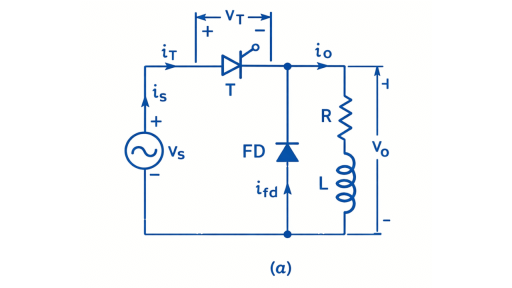
In this circuit, a rectifying device (diode or thyristor) is connected in series with a load consisting of resistance and inductance, and a freewheeling diode is connected in parallel with the load.
Circuit Diagram
The construction of this rectifier consists of a single phase AC source feeding a rectifying diode or controlled device connected in series with a load composed of resistance and inductance. A freewheeling diode is connected across the RL load in antiparallel direction such that it conducts when the load voltage reverses polarity.
Working of Single Phase Half Wave Rectifier with RL Load and Freewheeling Diode
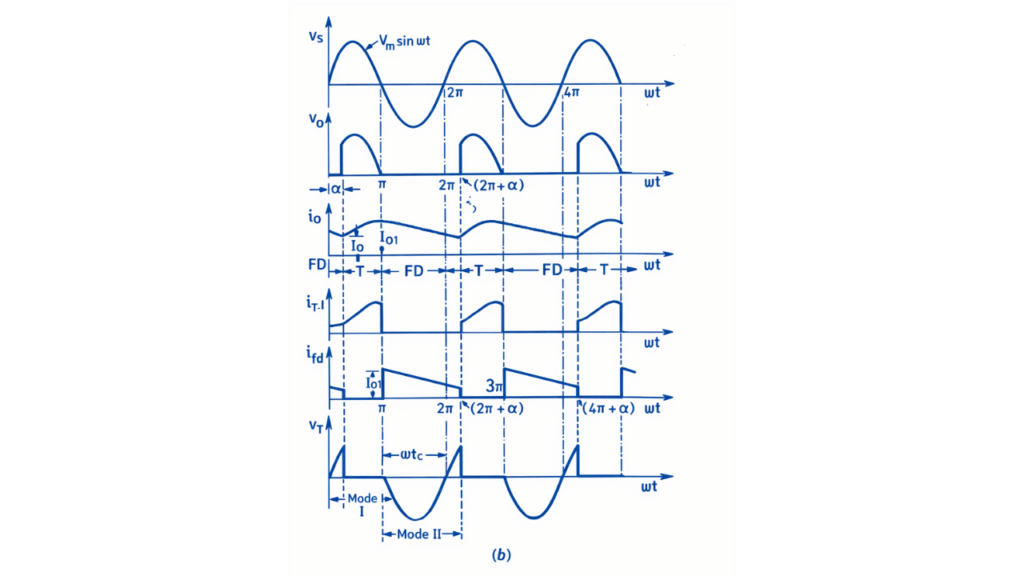
At the instant , the thyristor is triggered and begins to conduct. From this instant onward, the source voltage appears across the load as the output voltage vo. In the waveform, follows the positive half cycle of the source voltage from α to π. The load current starts increasing gradually due to the inductive nature of the load and lags behind the voltage waveform. During this interval, the thyristor current is equal to the load current, while the freewheeling diode remains reverse biased and carries no current.
At , the source voltage waveform crosses zero and begins to reverse polarity. In the voltage waveform, becomes negative after this point. However, the load current waveform does not fall to zero at because of the energy stored in the inductance. At this instant, the freewheeling diode becomes forward biased and starts conducting, while the thyristor is reverse biased and turns OFF. In the current waveforms, the current through the thyristor drops to zero at , and the entire load current is transferred to the freewheeling diode.
During the freewheeling interval from π to the next firing instant , the load current circulates through the RL load and the freewheeling diode. In the output voltage waveform, becomes zero throughout this interval because the load terminals are short-circuited by the freewheeling diode. The load current waveform shows a smooth exponential decay, indicating the gradual dissipation of the stored magnetic energy in the inductor. No negative voltage appears across the load during this period, and the source does not supply any power to the load.
At the next firing instant , the thyristor is again triggered, the freewheeling diode becomes reverse biased, and the conduction process repeats in the next cycle.
Output Waveform
Mathematical Derivation
Let the input supply voltage be
In this rectifier, output voltage exists only from
and during freewheeling period,
Average (DC) Output Voltage
Since output exists only from α to :
Integration
Since
Average (DC) Output Current
For resistive load :
RMS Output Voltage
Since output exists only from α to :
Simplify
Using identity
Integration
Applying limits:
Final RMS Voltage
For load resistance R: