Introduction
Insulation Resistance Test (IR Test) is a test used to measure the resistance offered by the insulation of electrical equipment such as motors, cables and transformers between live parts and earth, or between two live conductors, in order to assess the condition and health of the insulation.
In electrical equipment such as motors, cables and transformers, every wire is covered with insulation so that current flows only through the conductor and does not leak to the body or to other parts. The conductor carries current easily, while the insulation blocks it.
This is similar to a water pipe, where water flows inside the pipe and does not leak outside. In the same way, good insulation prevents leakage current. Since no insulation is perfect, a very small leakage current always exists. If the insulation becomes weak or damaged, this leakage increases. Therefore, insulation resistance testing is used to check how good the insulation is high resistance means healthy insulation, and low resistance means the insulation is deteriorating.
Basic Insulation Resistance Test Setup
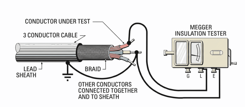
Fig:1 Insulation resistance test setup
Above diagram shows the standard connection diagram for an insulation resistance test.
Connection concept:
- L (Line) terminal of Megger → conductor under test
- E (Earth) terminal → earth / metallic body
- G (Guard) terminal → optional (used to bypass surface leakage)
This arrangement measures insulation resistance between conductor and earth.
Principle of Insulation Resistance Test
The insulation resistance test is based on Ohm’s law:
A high DC voltage is applied across the insulation and the resulting very small current is measured.
From this, insulation resistance is calculated.
A Megger (insulation tester) is essentially:
- a high-range ohmmeter
- with an internal DC generator
- calibrated directly in MΩ or GΩ
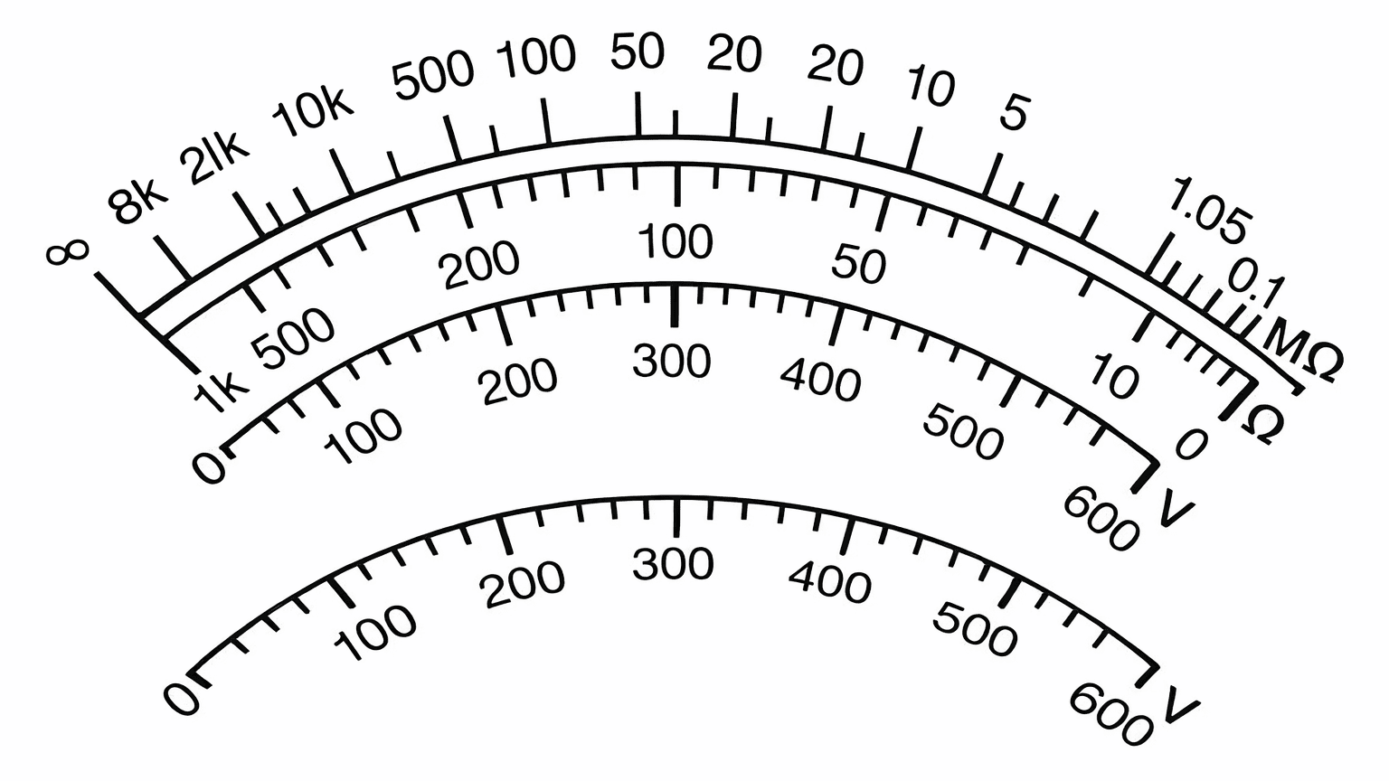
How Insulation Resistance is Measured
For good insulation, the resistance usually reads in the megohm range. The Megger insulation tester is essentially a high-range resistance meter (ohmmeter) with a built-in direct-current generator. This meter is of special construction with both current and voltage coils, enabling true ohms to be read directly, independent of the actual voltage applied. This method is non-destructive; that is, it does not cause deterioration of the insulation.
The generator can be hand-cranked or line-operated to develop a high DC voltage which causes a small current through and over surfaces of the insulation being tested (Fig. 1). This current (usually at an applied voltage
of 500 volts or more) is measured by the ohmmeter, which has an indicating scale. Fig. 2 shows a typical scale, which reads increasing resistance values from left up to infinity, or a resistance too high to be measured.
Short Practical Procedure (Field Method)
- Isolate and lock out the equipment.
- Discharge all conductors.
- Connect Megger:
- L → conductor
- E → earth/body
- Apply correct DC test voltage.
- Run test for 60 s (spot test).
- For large machines, record 1-min and 10-min values.
- Discharge the equipment again after the test.
- Record temperature and humidity.
Typical Connection Diagrams
DC Machine test
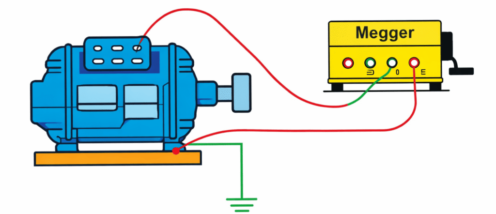
In a motor, an insulation resistance test checks the insulation between the motor windings and the motor body (earth). A high insulation resistance shows that the winding insulation is healthy, while a low value indicates moisture, dirt, or insulation damage inside the motor.
Power cable test
Fig:4 Insulation resistance test on cable
In a cable, the insulation resistance test measures the insulation between the conductor and the metallic sheath or earth, and also between different conductors. A high resistance means the cable insulation is in good condition, whereas a low resistance indicates aging, moisture ingress, or insulation failure.
Transformer winding test
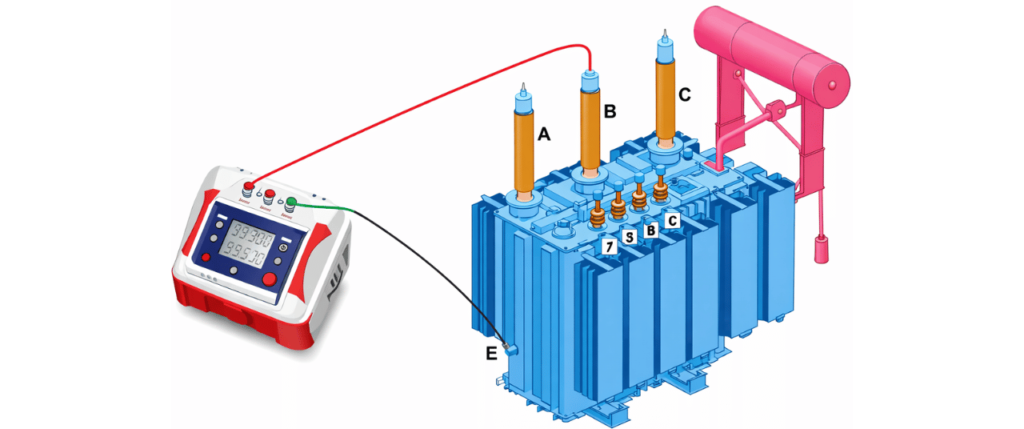
In a transformer, the insulation resistance test is used to check the insulation between the windings and earth, and also between the high-voltage and low-voltage windings. A high insulation resistance confirms good insulation condition, while a low value suggests deterioration of winding insulation or contamination inside the transformer.
IR Values for Electrical Apparatus & Systems
| Max. Voltage Rating of Equipment | Megger Size (Test Voltage) | Minimum IR Value |
|---|---|---|
| 250 Volts | 500 Volts | 25 MΩ |
| 600 Volts | 1,000 Volts | 100 MΩ |
| 5 kV | 2,500 Volts | 1,000 MΩ |
| 8 kV | 2,500 Volts | 2,000 MΩ |
| 15 kV | 2,500 Volts | 5,000 MΩ |
| 25 kV | 5,000 Volts | 20,000 MΩ |
| 35 kV | 15,000 Volts | 100,000 MΩ |
| 46 kV | 15,000 Volts | 100,000 MΩ |
| 69 kV | 15,000 Volts | 100,000 MΩ |
Safety Precautions
- Never connect a Megger to live equipment.
- Always discharge the equipment after the test.
- Large machines and long cables store dangerous energy.
- Do not perform tests in explosive or inflammable atmospheres.