All people living or working in residential, commercial and industrial installations especially operators and personnel who are in close contact with electrical systems and equipment must be adequately protected against the dangers of electric shock. To ensure this protection, a properly designed and correctly installed earthing system is required in every electrical installation in accordance with standard safety requirements.
What is Earthing?
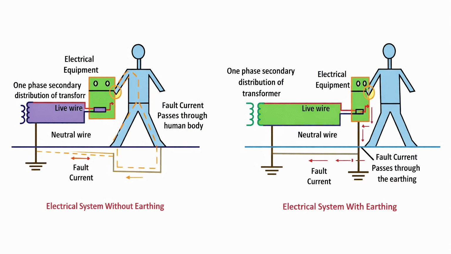
The process of connecting metallic bodies of all the electrical apparatus and equipment to huge mass of earth by a wire having negligible resistance is called Earthing.
In simple words, earthing provides a safe path for fault current to flow into the ground. When insulation fails and a live conductor touches the metal body, the fault current flows through the earthing system instead of passing through a human body.
Importance of Earthing
- Earthing is important because it protects human beings from electric shock by providing a low-resistance path for fault current to flow safely into the ground.
- It keeps the exposed metal parts of electrical equipment at nearly earth potential, so the risk of dangerous touch voltage is reduced.
- Earthing ensures quick and reliable operation of protective devices such as fuses, MCBs and relays by allowing sufficient fault current to flow.
- It protects electrical equipment from damage due to insulation failure, leakage current and abnormal fault conditions.
- Earthing helps in stabilising the system voltage with respect to ground, especially in systems where the neutral is earthed.
- It also reduces the risk of fire caused by fault currents flowing through unintended paths.
Types of Earthing (Methods)
The commonly used types of earthing in electrical installations are:
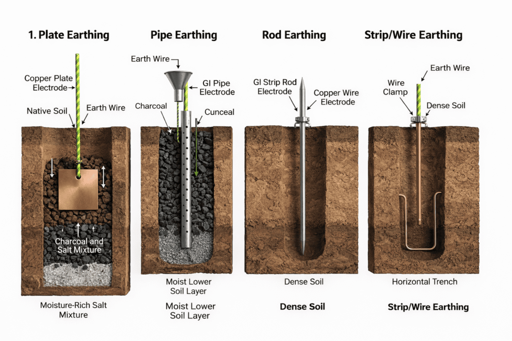
- Plate earthing – In this method, a copper or galvanized iron (GI) plate is buried vertically in the ground and connected to the equipment body through an earthing conductor. Charcoal and salt are placed around the plate to reduce earth resistance.
- Pipe earthing – In this method, a perforated GI pipe is buried vertically in moist soil and connected to the earthing conductor. It is the most economical and widely used method in residential, commercial and industrial installations.
- Rod earthing – In this method, a copper or galvanized steel rod is driven directly into the ground to form the earth electrode. It is suitable where space is limited and multiple rods can be used to obtain low resistance.
- Strip (or wire) earthing – In this method, a copper or GI strip or wire is laid horizontally in a trench in the ground. It is mainly used for large installations such as substations and power stations where high fault currents are expected.
Plate Earthing
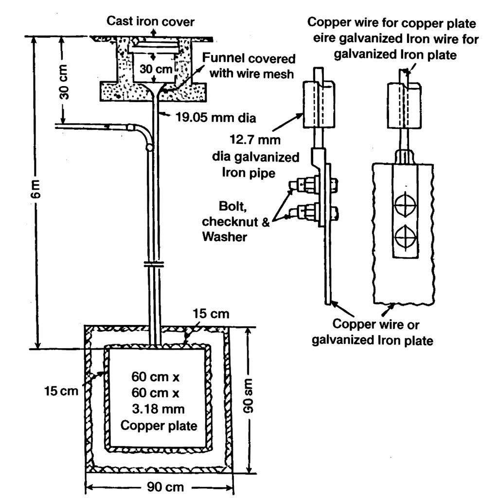
The diagram shows a plate earthing arrangement constructed below ground level.
At the top, a cast-iron (CI) cover and concrete inspection chamber are provided. Inside this chamber there is a funnel covered with wire mesh. This funnel is used for pouring water so that moisture is maintained around the electrode. From the funnel, a galvanized iron (GI) pipe runs vertically downward into the earth pit. This pipe guides water directly near the earth electrode.
At the bottom of the pit, a copper plate or galvanized iron (GI) plate is placed vertically. The usual size shown in the diagram is about 600 mm × 600 mm (with suitable thickness for copper or GI). The plate is surrounded on all sides by a layer of charcoal and salt (normally about 15 cm thick). This layer reduces the earth resistance and helps retain moisture.
The earthing conductor (copper wire or GI wire/strip) is connected to the plate by a bolt, nut, check-nut and washer arrangement. This connection is brought up to ground level through a protective path and is taken to the equipment earthing terminal.
Thus, the main parts visible in the diagram are: inspection chamber with cover, funnel and wire mesh, GI watering pipe, earthing lead, bolted joint, charcoal and salt layers, and the copper or GI earth plate placed in moist soil.
Procedure to install plate earthing
- First, a pit of suitable size and depth is dug at the selected location. Normally the depth is about 2.5 m to 3 m so that the electrode remains in permanently moist soil.
- Next, a copper plate or GI plate of standard size is placed vertically at the bottom of the pit.
- After placing the plate, the space around it is filled with alternate or mixed layers of charcoal (or coke) and common salt on all sides, up to about 15 cm thickness around the plate.
- Then the earthing conductor is firmly connected to the plate using bolts, nuts, check-nuts and washers to ensure a low-resistance and corrosion-free joint.
- A GI watering pipe with a funnel and wire mesh at the top is installed so that water can be poured directly near the electrode.
- The earthing conductor is brought up to ground level and routed to the installation through a protective path, and a small inspection chamber with a CI cover is constructed at the top for access and maintenance.
- Finally, the pit is filled with soil and compacted. Water is poured through the funnel to make the surrounding soil moist.
- After completion, the earth resistance is measured to confirm that the earthing system is satisfactory.
- This completes the installation of plate earthing.
Advantages
- Low and stable earth resistance
- Large contact area with soil
- Long life (especially copper plate)
- Reliable for important installations
Disadvantages
- Costly compared to pipe earthing
- Requires more excavation and space
- Installation is time-consuming
- Needs regular watering
Applications
- Residential and commercial buildings
- Substations and transformer installations
- Power panels and important equipment earthing
Pipe Earthing
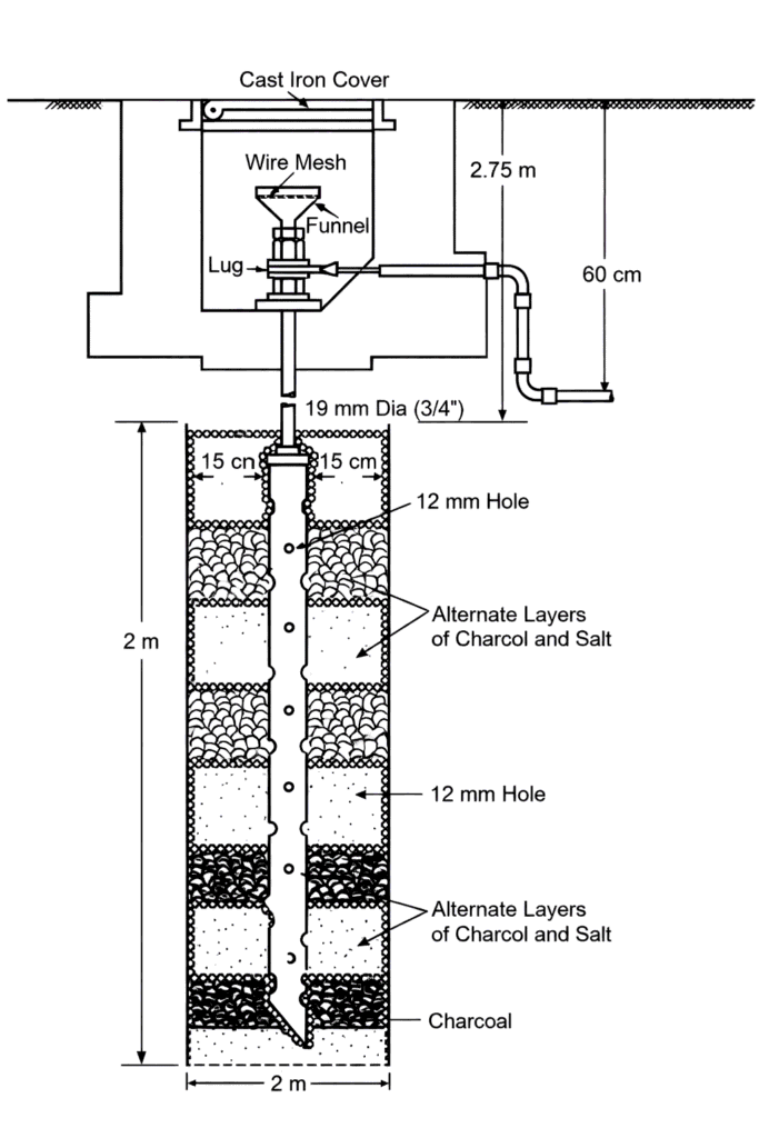
In this figure, the earthing electrode is a perforated galvanized-iron (GI) pipe installed vertically in the ground.
At ground level, a small inspection chamber is provided and closed with a cast-iron cover. Inside the chamber, a funnel covered with wire mesh is fixed. This funnel is used for pouring water and the mesh prevents stones or debris from entering the pipe. From the funnel, the GI pipe (about 19 mm diameter in the figure) goes vertically down into the earth.
The pipe has holes (about 12 mm) along its length so that water poured through the funnel can spread into the surrounding soil. Around the GI pipe, the pit is filled with alternate layers of charcoal and salt. These layers improve soil conductivity and reduce earth resistance. The lower end of the pipe is kept inside moist soil, and the total depth of the electrode is about 2 m to 3 m as indicated in the figure.
The earthing conductor is connected to the pipe through a proper lug and clamping arrangement near the top portion.
Procedure to install pipe earthing
- First, select a suitable location where the soil is reasonably moist and free from underground services.
- Dig a vertical pit of about 2 to 3 metres depth.
- Place the perforated GI pipe vertically at the centre of the pit.
- Connect the earthing conductor to the GI pipe using a proper clamp and lug.
- Fill the space around the pipe with alternate layers of charcoal and salt up to the required height.
- Fix the funnel with wire mesh at the top of the pipe and construct a small inspection chamber with a cast-iron cover at ground level.
- Fill the remaining portion of the pit with soil and compact it.
- Finally, pour water through the funnel so that moisture is maintained around the pipe.
- After installation, measure the earth resistance to confirm that proper earthing has been achieved.
This completes the construction and installation of a pipe-earthing system.
Advantages
- Low cost
- Easy installation
- Low earth resistance
- Easy maintenance
Disadvantages
- Not suitable for rocky soil
- Needs regular watering
- GI pipe may corrode
Applications
- Houses and buildings
- Factories and workshops
- Earthing of motors and panels
Rod Earthing
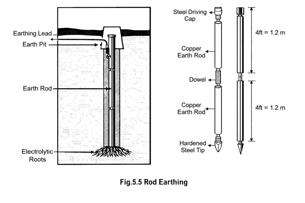
Rod earthing is a method of earthing in which a metal rod (usually copper or copper-clad steel) is driven vertically into the ground and connected to the earthing conductor.
The rod itself acts as the earth electrode. Because it goes deep into the soil, it provides a low-resistance path for fault current to flow safely into the earth.
In the shown diagram, the main parts are:
- a copper / copper-clad steel earth rod driven into the ground,
- a clamp or lug at the top of the rod for connecting the earthing conductor,
- in some installations, couplers are used to join more than one rod so that greater depth can be achieved,
- a driving cap and hardened steel tip are used while driving the rod.
Procedure for installing rod earthing
- First, select a suitable location near the equipment where the soil is not extremely dry and is free from underground pipes or cables.
- Make a small pit or opening at ground level.
- Place the earth rod vertically at the chosen point and drive it into the ground using a hammer or mechanical driver.
If the required depth is not achieved with one rod, connect another rod using a coupler and continue driving. - Drive the rod until the top of the rod is just below or at ground level.
- Connect the earthing conductor (copper or GI wire/strip) to the rod using a proper clamp and lug so that the contact is tight and has low resistance.
- Provide a small inspection pit or cover at the top for future checking.
- Finally, check the earth resistance using an earth tester to ensure that the earthing is satisfactory.
This completes the installation of rod earthing.
Advantages
- Simple and fast installation
- Requires very little space
- Suitable for hard and rocky soil
- Less excavation is needed
Disadvantages
- Earth resistance may be high in dry or sandy soil
- Not suitable where very low earth resistance is required
- Sometimes more than one rod is needed
Applications
- Rocky and hilly areas
- Small electrical installations
- Temporary installations
- Earthing of poles, towers and small equipment
Strip (or wire) Earthing
Strip earthing is a method in which a long copper or GI strip (or wire) is buried horizontally in the ground and used as the earth electrode. The strip is laid in a trench and connected to the earthing conductor of the installation. Because the strip has large contact area with soil, it provides a low-resistance path for fault current.
This method is mainly used where a large earthing network is required, such as substations and power plants.
Installation procedure of strip earthing
- First, a trench is dug in the ground (generally about 0.5 m to 1 m deep and of required length).
- A copper or GI strip (or wire) of standard size is laid horizontally along the bottom of the trench.
- The strip is properly joined and connected to the main earthing conductor using clamps or welded joints.
- If required, a thin layer of soft soil (or conductive backfill) is placed around the strip.
- The trench is then filled with soil and well compacted.
- Finally, the earthing conductor from equipment is connected to the strip, and the earth resistance is measured.
This completes the strip (wire) earthing installation.
Advantages
- Large contact area with soil
- Low earth resistance for large installations
- Suitable for substations and plants
- Long life and reliable
Disadvantages
- Requires long trench and more space
- Higher installation cost
- Not suitable for small installations
Applications
- Substations
- Power stations
- Industrial plants
- Large electrical installations
Factors on which earth resistance depends
a) Type of soil
b) Temperature of soil
c) Wetness of soil
d) Minerals in earth
e) Shape of earth electrode
f) Size of earth electrode
g) Depth of electrode in earth
h) Diameter of earth electrode
i) Number of ground electrodes
j) Distance between two electrodes
Comparison between Earthing and Grounding.
| Basis | Earthing | Grounding |
|---|---|---|
| 1. Definition | Connection of non-current carrying metallic parts of equipment to earth | Connection of a current-carrying point of the system (usually neutral) to earth |
| 2. Connected part | Equipment body, frame, enclosure | Neutral or star point of generator/transformer |
| 3. Main purpose | Protects people from electric shock | Maintains system stability and limits over-voltage |
| 4. Type of parts involved | Non-live metal parts | Live part of the system |
| 5. Current flow | Normally no current flows | Current can flow during fault or unbalance |
| 6. Protection provided | Personal and equipment protection | System and network protection |
| 7. Use in installation | Used for motors, panels, appliances, structures | Used in generators, transformers and power systems |
| 8. Effect on system voltage | Does not control system voltage | Helps control voltage with respect to earth |
| 9. Failure consequence | Equipment body may become dangerous | System becomes unstable and protection may fail |