Introduction
A transformer is rightly known as the backbone of the power system. As an electrical engineering student, you quickly realize that generation, transmission, and distribution of electrical power would not be possible in their present form without transformers.
In power systems, an AC system is preferred over a DC system mainly because the voltage level can be easily changed using a transformer. For economic reasons, electrical power is transmitted at high voltage to reduce transmission losses, while for safety and utilization, the voltage must be stepped down to lower levels.
This continuous voltage adjustment at different stages is carried out by transformers, making them an essential part of modern power systems.
What is a Transformer?
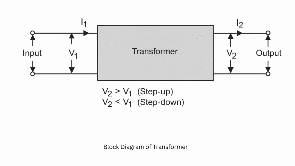
A transformer is a static electrical device that transfers electrical energy from one circuit to another without any direct electrical connection, using the principle of electromagnetic induction. It operates only on alternating current (AC) and is used to increase or decrease voltage levels without changing frequency.
Principle of Operation
A transformer works on the principle of mutual induction, which is based on Faraday’s Law of Electromagnetic Induction.
When an alternating current flows in one coil, it produces a changing magnetic field, which induces an emf in a near by coil.
Necessity of a Transformer
In our country, electrical power is generally generated at about 11 kV. However, transmitting this power directly at such a low voltage over long distances would result in huge power losses and poor efficiency. To overcome this problem, the voltage level is stepped up to very high values such as 220 kV, 400 kV, or even 750 kV using step-up transformers before transmission.
Once the power reaches near the load centers, it cannot be supplied directly at such high voltages. Therefore, to meet the requirements of different regions, the voltage is stepped down in stages to 66 kV, 33 kV, or 11 kV using step-down transformers installed at substations. Finally, for safe utilization in homes, offices, and industries, the voltage is further reduced to 400/230 V.
From generation to final consumption, every stage of the power system depends on transformers for voltage control. This clearly shows that a transformer plays a crucial and unavoidable role in the power system, ensuring efficient transmission, proper distribution, and safe utilization of electrical energy.
Construction of a Transformer
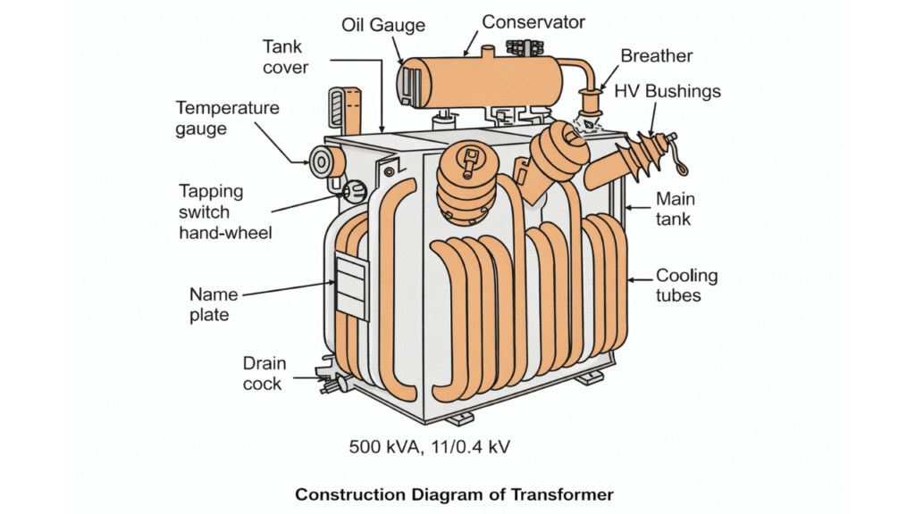
The following are the major elements of a transformer:
(i) Magnetic circuit mainly comprises of transformer core having limbs and yokes.
(ii) Electric circuits mainly comprises of windings, insulation and bushings.
(iii) Tank mainly comprises of cooling devices, conservator and ancillary apparatus.
The Magnetic Circuit (The Core)
- Lamination: The core is made of thin silicon steel laminations (usually 0.35 mm to 0.5 mm thick). Each sheet is coated with an insulating varnish to reduce eddy current losses.
- Limbs and Yokes: The vertical portions where the windings are placed are called limbs (or legs), while the horizontal pieces that connect the limbs and complete the magnetic path are called yokes.
- Core Type: The windings surround a considerable part of the core.
- Shell Type: The core surrounds a considerable portion of the windings.
The Electric Circuit (Windings and Insulation)
- Windings: Generally made of high-grade copper or aluminum. The primary winding is connected to the source, and the secondary winding is connected to the load.
- Insulation: This is critical for safety and performance. Insulation is required between:
- Individual turns of the wire.
- The primary and secondary windings.
- The windings and the core.
- Bushings: These are porcelain or composite insulators that allow the internal conductors to pass through the metal tank without touching it, connecting the transformer to the external power lines.
The Tank and Cooling System
- The Tank: A robust steel container that houses the core and windings, usually filled with transformer oil.
- Transformer Oil: Serves a dual purpose: it acts as an excellent insulator and a coolant to carry heat away from the core.
- Conservator Tank: A small tank located above the main tank. It allows the oil to expand and contract with temperature changes without exposing the main tank to air.
- Breather: Contains silica gel to extract moisture from the air as the transformer “breathes” during temperature cycles.
- Radiators/Cooling Fins: Increase the surface area for heat dissipation.
Working of a Transformer
The basic principle of a transformer is electromagnetic induction.
A single-phase transformer consists of two windings placed over a laminated silicon steel core. The winding having less number of turns is called low-voltage winding and the winding having more number of turns is called high voltage winding
Also, the winding to which AC supply is connected is called a primary winding and the other one is called a secondary winding to which load is connected. Once AC supply of voltage is given to primary winding, an alternating flux is set-up in the magnetic core which links with the primary and secondary winding. Consequently, self-induced emf and mutually-induced emf are induced in primary and secondary, respectively. These induced emf’s are developed in phase opposition to as per Lenz’s law. The self-induced emf in the primary is also called back emf since it acts in opposite direction to the applied voltage.
Although, there is no electrical connection between primary and secondary winding, still electric power is transferred from one circuit (primary side) to the other circuit (secondary side). It is all because of magnetic coupling, i.e., the alternating flux which is set-up in the core linking with both the windings. The magnitude of induced emf in a coil depends upon rate of change of flux linkages i.e., . Since, the rate of change of flux for both the windings is the same, the magnitude of induced emf in primary and secondary will depend upon their number of turns, i.e., primary induced emf and secondary induced emf . When , the transformer is called a step-up transformer, on the other hand, when the transformer is called step-down transformer.
Turn ratio: The ratio of primary to secondary turns is called turn ratio, i.e.,
Transformation ratio: The ratio of secondary voltage to primary voltage is called voltage transformation ratio of the transformer. It is represented by .
….(since and )
Types of Transformers
Based on Voltage Transformation
- Step-Up Transformer (E₂ > E₁ and N₂ > N₁)
- Step-Down Transformer (E₂ < E₁ and N₂ < N₁)
- Isolation Transformer (E₂ = E₁)
Based on Construction
- Core-Type Transformer
- Shell-Type Transformer
Based on Number of Phases
- Single Phase Transformer
- Three Phase Transformer
Based on Application
- Power Transformer
- Distribution Transformer
- Instrument Transformer (CT) and (PT)
Based on Winding Arrangement
- Auto Transformer
- Two-Winding Transformer
Based on Cooling Method
- Air-Cooled Transformer
- Oil-Cooled Transformer
Advantages of Transformer
- High Efficiency
Transformers are highly efficient devices (often above 95%) as they have no moving parts. - Voltage Level Change
They can easily step-up or step-down voltage as required. - Electrical Isolation
Provides isolation between primary and secondary circuits, improving safety. - Low Maintenance
Due to no rotating parts, maintenance is minimal. - Long Life
Transformers have a long operational life if properly maintained. - Flexible Installation
They can be used for various applications ranging from small chargers to power stations.
Disadvantages of Transformer
- Works Only on AC Supply
Transformers cannot operate on DC. - Bulky and Heavy
Especially power transformers are large in size and weight. - Costly for High Ratings
High-capacity transformers are expensive. - Copper and Core Losses
Energy is lost due to hysteresis, eddy currents, and copper losses. - Noise
Some transformers produce humming noise due to magnetostriction. - Oil Leakage (Oil-Cooled Transformers)
Can cause environmental and safety issues if not maintained properly.
Applications of Transformer
- Power Transmission & Distribution
- Domestic Use
- Industrial Applications
- Electronics & Communication
- Measurement & Protection