Introduction
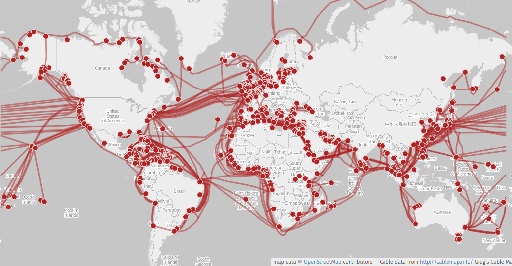
A transmission line is used to carry electrical power or signals from one place to another over a long distance. Examples include overhead power lines, underground cables, telephone lines, and communication cables.
When the line is very short, we can treat it like a normal circuit with resistors, inductors, and capacitors placed at one point. But when the line is long, this method is not accurate. This is because the electrical effects are spread all along the length of the line. Therefore, a long transmission line is modeled using distributed parameters.
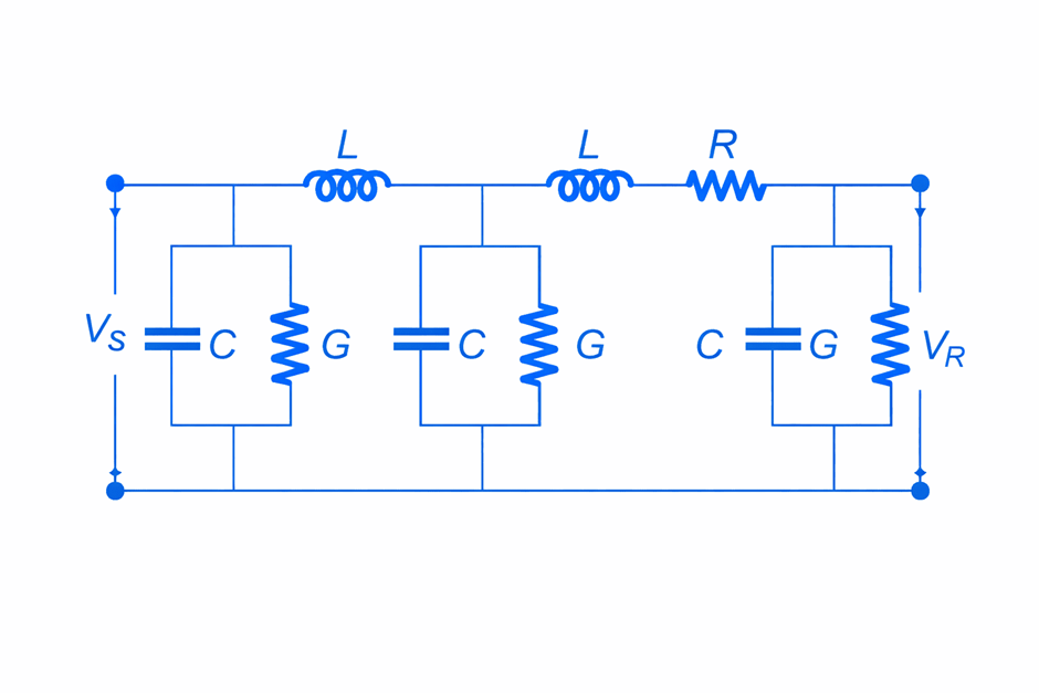
An electric transmission line can be modeled by a series combination of resistance (R) and inductance (L), along with a shunt combination of conductance (G) and capacitance (C). These four primary parameters R, L, G, and C are uniformly distributed along the entire length of the line. The values of these parameters depend on the line geometry, the materials used in construction, and the operating frequency.
Resistance (R) of a Transmission Line
The resistance of a transmission line represents the opposition offered by the conductor to the flow of electric current. Due to this resistance, some electrical power is lost in the form of heat. This power loss is called copper loss.
The effective resistance of a conductor is given by:

where:
= resistivity of the conductor material
= length of the conductor
= cross-sectional area of the conductor
In practice, the effective resistance is slightly greater than the DC resistance because of skin effect and proximity effect, especially at higher frequencies.
- Skin effect causes current to flow more on the surface of the conductor.
- Proximity effect causes uneven current distribution due to nearby conductors.
In transmission lines, the value of resistance is generally small. Therefore, it mainly affects the efficiency of power transmission by causing power loss. For most practical calculations of voltage regulation, the effect of resistance is often neglected because it is relatively small compared to reactance.
Inductance (L) of a Transmission Line
Inductance of a transmission line is due to the magnetic field produced around the conductors when current flows through them. This magnetic field stores energy and opposes any change in current.
The inductance depends on:
- Spacing between conductors
- Radius of the conductors
- Arrangement of the line (single-phase or three-phase)
Inductance causes a reactive voltage drop in the line, which affects the voltage regulation of the transmission system. Unlike resistance, inductance does not cause power loss but stores and releases energy.
At higher frequencies, inductance is affected slightly by skin effect and proximity effect, which change the current distribution inside the conductor.
Capacitance (C) of a Transmission Line
Capacitance exists between the conductors of a transmission line and between the conductor and ground. It is due to the electric field formed because of the voltage difference between conductors.
Capacitance depends on:
- Distance between conductors
- Radius of conductors
- Permittivity of the insulating medium (air or insulation material)
Capacitance causes a charging current to flow even when the line is lightly loaded or open-circuited. This charging current affects:
- Voltage profile along the line
- Power factor
- Reactive power flow
In long transmission lines, capacitance plays an important role and cannot be neglected.
Conductance (G) of a Transmission Line
Conductance represents the leakage current flowing through the insulating material between conductors and between conductor and ground.
It depends on:
- Quality of insulation
- Atmospheric conditions (rain, humidity, pollution)
- Temperature
In overhead transmission lines, conductance is usually very small and is often neglected in practical calculations. However, in underground cables, conductance may be significant due to insulation leakage and dielectric losses.
Conductance causes power loss in the dielectric and reduces the overall efficiency of the transmission line.
Steady-State Performance of Overhead Transmission Lines
The steady-state performance of a transmission line refers to the study of how the line behaves under normal operating conditions. The performance of a line is mainly judged by two important factors:
- Efficiency
- Voltage Regulation
Efficiency of a Transmission Line
Efficiency indicates how effectively electrical power is transmitted from the sending end to the receiving end. It is defined as the ratio of power received at the load end to the power supplied at the sending end.

Higher efficiency means less power loss in the transmission line.
Voltage Regulation of a Transmission Line
Voltage regulation shows the change in receiving end voltage when the load varies from no-load to full-load condition, while the sending end voltage remains constant.

where:
= Receiving end voltage at no load
= Receiving end voltage at full load
Lower voltage regulation indicates better voltage stability and performance of the line.
Effect of Line Length and Frequency
Electrical power travels along the transmission line at nearly the speed of light, that is:

For a supply frequency of 50 Hz, the wavelength is:
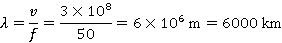
This means one complete wave occupies a length of about 6000 km.