Three Phase VSI using Sine Triangle PWM (SPWM)
A three-phase Voltage Source Inverter (VSI) is a type of inverter that converts DC voltage into three-phase AC voltage with sinusoidal waveforms. It works by varying the pulse width of a high-frequency carrier signal according to the instantaneous amplitude of a reference sinusoidal waveform. In a 3-phase inverter, three separate SPWM signals are generated for each phase, By comparing a high-frequency triangular waveform with three sinusoidal reference waveforms (one for each phase) to determine the pulse widths of the inverter’s switching devices.
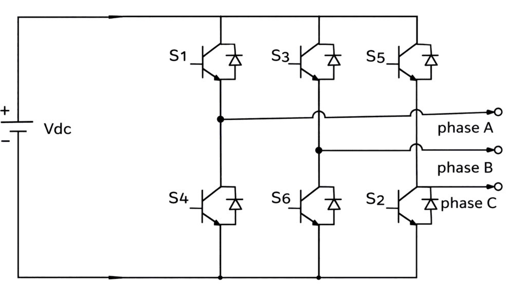
A three-phase VSI consists of six power semiconductor switches, typically insulated-gate bipolar transistors (IGBTs) or power MOSFETs, arranged in an H-bridge configuration. The switches are grouped into three pairs, each controlling one phase of the output voltage (Va, Vb, and Vc). To generate the desired three-phase sinusoidal output, three reference sinusoidal waveforms (Vra, Vrb, and Vrc) are generated. These reference waveforms have a fixed frequency (ω) and amplitude (Vm) and are phase-shifted by 120 degrees relative to each other.
The reference waveform for each phase is given by:
Vra(t)=Vmsin(ωt)
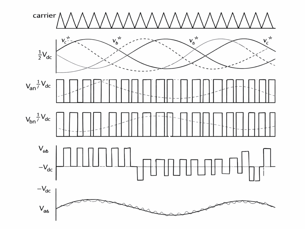
A high-frequency triangular carrier waveform (Vcarr) is generated with a frequency (fc) much higher than the desired output frequency of the inverter. The carrier waveform varies between -Vc and +Vc, where Vc is the peak amplitude of the carrier waveform.
The instantaneous values of the reference sinusoidal waveforms (Vra, Vrb, and Vrc) are continuously compared with the triangular carrier waveform (Vcarr) using comparators. Based on the comparison, the inverter switches are turned ON or OFF for specific durations, determining the pulse width of the output voltage. When the reference waveform is greater than the carrier waveform, the corresponding switch is turned ON. When the reference waveform is smaller, the switch is turned OFF, during the positive half-cycle of the reference waveform Vra(t), the switch S1 (top switch) and S4 (bottom switch) for phase A are turned ON if Vra(t) > Vcarr(t). The switches will remain ON until Vra(t) < Vcarr(t) during the negative half-cycle.
The same process is applied to the other phases, with switches S2, S5, S3, and S6 for phases B and C, respectively.
Advantages of Three Phase VSI with SPWM
- Produces high-quality sinusoidal output with low harmonic distortion
- Allows easy control of output voltage and frequency
- Flexible operation by adjusting modulation index and carrier frequency
- Requires smaller and simpler output filters due to low harmonics
Disadvantages of Three Phase VSI with SPWM
- High switching losses due to high switching frequency
- Increases system cost and design complexity
- Performance is sensitive to parameter variations (temperature, load, components)
- Needs advanced control techniques for stable operation
- Requires proper cooling systems to handle heat dissipation
Applications of Three Phase VSI with SPWM
- Used in motor drives for controlling speed and torque of AC motors
- Applied in induction motors and PMSMs for smooth operation
- Used in solar inverters and wind energy systems for DC to AC conversion
- Used in aircraft power systems and electronic equipment