Slip Power Recovery of an Induction Motor
When speed control is required, especially in wound rotor induction motors, a significant amount of power known as slip power is lost in the rotor circuit.
To improve efficiency and utilize this wasted energy, a technique called Slip Power Recovery is used. In this method, the power that would normally be dissipated as heat in the rotor resistance is recovered and fed back to the supply or reused in the system.
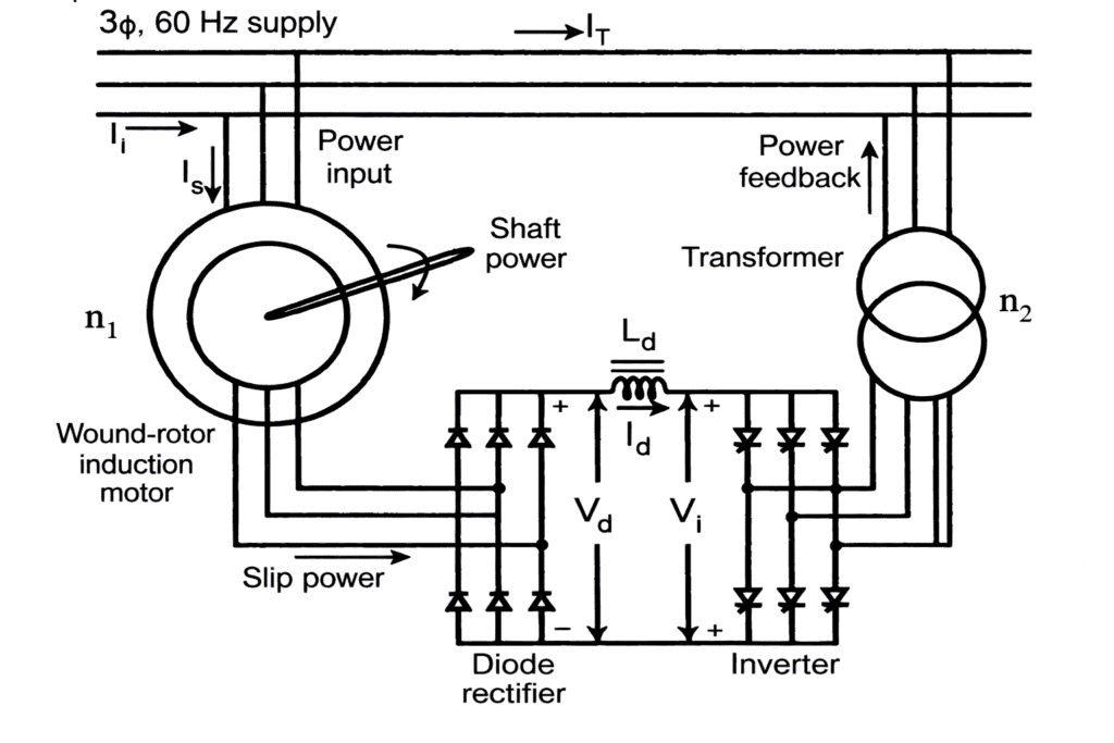
The basic principle of slip power recovery is to connect an external source of EMF having the same frequency as the rotor slip frequency. This technique enables the recovery of slip energy from the rotor circuit of a slip ring induction motor. The slip energy recovery method allows speed control of a slip ring induction motor below its synchronous speed. In this system, a portion of the rotor AC power, called slip power, is converted into DC using a diode bridge rectifier.
A smoothing reactor is used to reduce ripples and smooth the rectified current. The DC output from the rectifier is then supplied to the DC terminals of the inverter. The inverter converts the DC power back into AC power and returns it to the AC supply source. In this arrangement, the inverter operates as a controlled rectifier working in inversion mode.
This speed control technique is commonly used in high power applications, where wide speed variation results in a considerable amount of slip power that can be effectively recovered and reused.
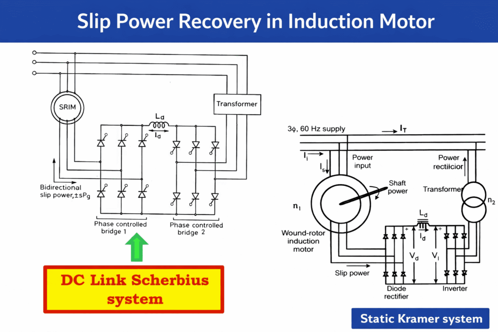
There are two types of Slip power recovery scheme:
1.Static Karmer Drive
2. Static Scherbius Drive
1. Static Karmer Drive
A Static Kramer Drive is a slip power recovery system designed to control the speed of wound rotor induction motors. It operates by extracting the rotor’s slip power, converting it using power electronics, and feeding it back into the supply line. This drive is an effective solution for processes requiring precise speed control and improved energy efficiency.
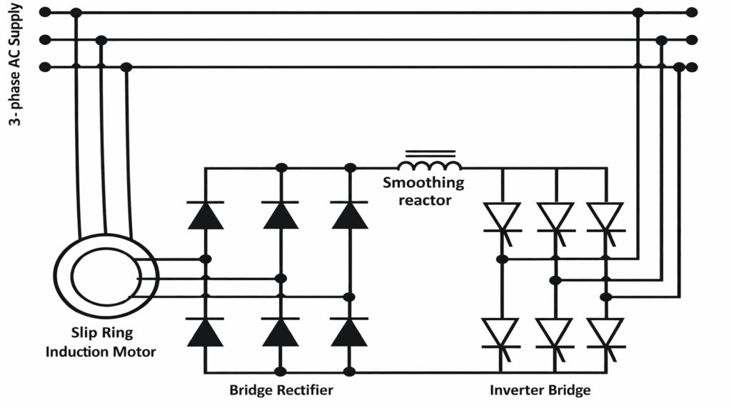
Working Principle of Static Kramer Drive
In the Static Kramer Drive, the stator of the wound rotor induction motor is connected directly to the three phase supply. When the motor runs below synchronous speed, slip power appears in the rotor circuit. This slip power is taken from the rotor through slip rings and converted into DC using a diode rectifier.
The DC power then flows through a smoothing inductor and is converted back into AC by a line commutated inverter. Finally, the recovered power is fed back to the supply through a transformer. Since the slip power is returned to the supply, the system improves efficiency. The Static Kramer Drive can control the motor speed only below synchronous speed.
Advantages of Static Kramer Drive
- Variable Speed Control: It provides smooth and accurate control of motor speed.
- Cost Effective Operation: The system reduces energy losses and lowers operational costs.
- Reduced Heat Dissipation: Less heat is generated in the rotor circuit due to slip power recovery.
- Suitable for High Power Applications: It is widely used with large motors in industrial applications.
- Compact Design: Power electronic components make the system smaller and simpler.
Disadvantages of Static Kramer Drive
- Limited Speed Range: It can control motor speed only below synchronous speed within the slip range.
- Harmonics Generation: Rectifiers and inverters used in the system introduce harmonics into the power supply.
- Dependency on Supply Quality: The drive requires a stable and good quality power supply for proper operation.
- High Initial Cost: The system has a higher initial installation cost compared to conventional speed control methods.
2. Static Scherbius Drive
A Static Scherbius Drive is a slip power recovery system used to control the speed of a wound rotor induction motor by converting rotor slip power through power electronic converters and feeding it back to the supply, allowing speed control both below and above synchronous speed.
Working Prinple of Static Scherbius Drive
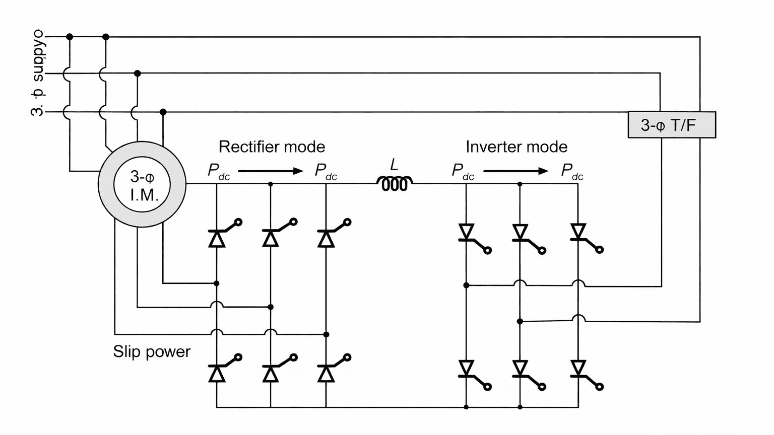
In the Static Scherbius Drive, the rotor slip power is also taken through slip rings, but it is processed using two phase controlled converters connected through a DC link. One converter works as a rectifier and the other works as an inverter depending on the operating condition. The slip power can either be fed back to the supply or drawn from the supply. Because of this bidirectional power flow, the Static Scherbius Drive can control the motor speed both below and above synchronous speed. This makes the system more flexible for wide speed range applications.
Thus, the main difference is that the Static Kramer Drive allows only sub synchronous speed control with slip power fed back to the supply, while the Static Scherbius Drive allows both sub synchronous and super synchronous speed control due to bidirectional power flow in the converter system.
Advantages of Static Scherbius Drive
- Allows speed control both below and above synchronous speed.
- High efficiency because slip power is recovered and reused.
- Provides smooth and wide range speed control.
- Reduces power loss compared to rotor resistance control.
Disadvantages of Static Scherbius Drive
- The system is complex due to power electronic converters.
- Harmonics are produced in the power supply.
- Initial installation cost is high.
- Requires a wound rotor induction motor with slip rings.
- Maintenance is higher compared to simple speed control methods.
Comparison Between Static Kramer Drive & Static Scherbius Drive
| Aspect | Static Kramer Drive | Static Scherbius Drive |
|---|---|---|
| Slip Power Utilization | Slip power is recovered and returned back to the supply system | Slip power is fed back into the rotor circuit |
| Speed Range | Operates only below synchronous speed | Can operate both below and above synchronous speed |
| Efficiency | High efficiency because power is directly returned to the supply | Comparatively moderate due to extra losses in the feedback path |
| Complexity | Simpler structure with fewer components | More complex due to the use of additional converters |