Introduction
A single phase half wave controlled rectifier is a power electronic circuit that converts single phase AC into controlled DC using a thyristor (SCR). In this rectifier, conduction takes place only during the positive half cycle of the AC input and starts at a controllable firing angle α. By varying the firing angle, the average output DC voltage can be regulated. It is mainly used in low-power controlled DC applications.
In a single phase half wave controlled rectifier with resistive (R) load, a thyristor (SCR) is used to control the conversion of AC into DC. Since the load is purely resistive, the load current is always in phase with the load voltage. The conduction of the SCR depends on the firing angle α and the polarity of the input voltage.
Circuit Diagram and Components
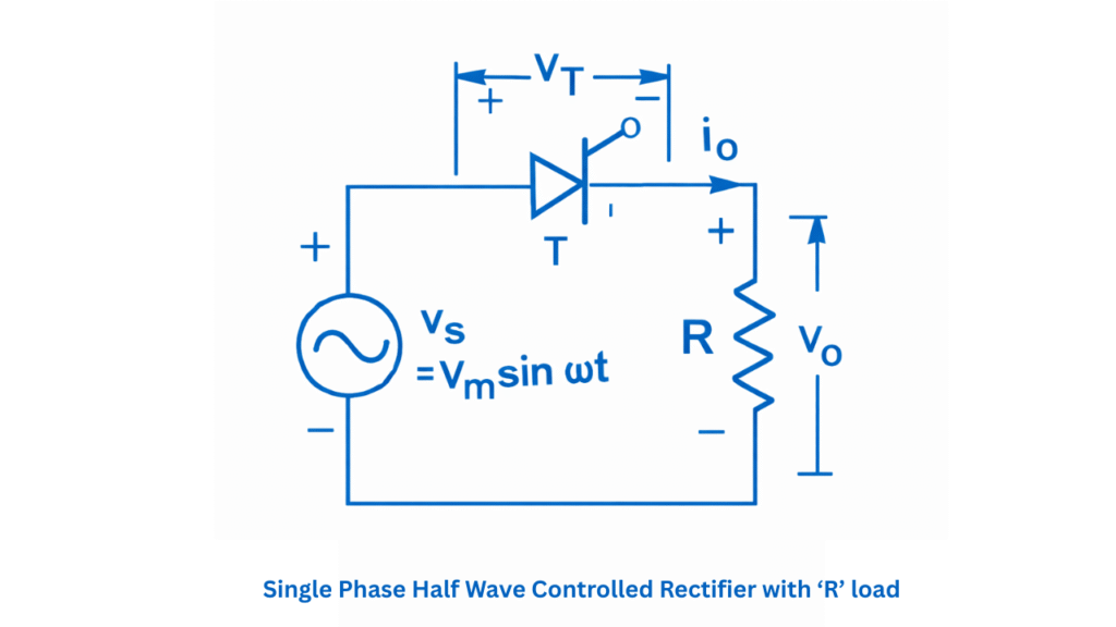
The basic circuit consists of :
- Single phase AC supply
- Transformer (optional, for isolation and voltage adjustment)
- One thyristor (SCR)
- Resistive load
- Gate triggering circuit
Working Principle
Operation During Positive Half Cycle
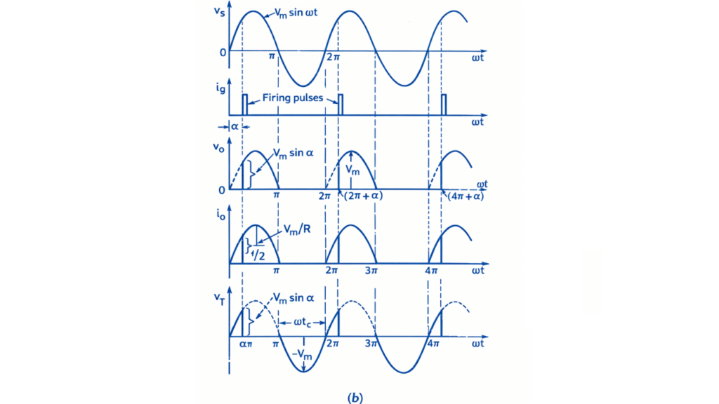
During the positive half cycle, the anode of the thyristor becomes positive with respect to the cathode and the device is forward biased. However, it remains in the forward blocking state until a gate triggering pulse is applied. From the beginning of the positive half cycle up to the firing angle α, the thyristor remains OFF and no current flows through the load, so the output voltage remains zero.
At the instant ωt = α, a gate pulse is applied and the thyristor turns ON. Current then flows through the thyristor and the resistive load, and the output voltage follows the instantaneous value of the input sinusoidal voltage. Since the load is purely resistive, the load current is in phase with the load voltage. Conduction continues until the end of the positive half cycle at ωt = π, when the current naturally falls to zero and the thyristor turns OFF by natural commutation.
Operation During Negative Half Cycle
During the negative half cycle, the thyristor becomes reverse biased and remains in the OFF state throughout this interval. No current flows through the load and the output voltage remains zero. At the end of the negative half cycle, the input voltage again becomes positive and the thyristor is ready for triggering in the next cycle. Thus, conduction occurs only from the firing angle α to π in each positive half cycle, and the average output DC voltage is controlled by varying the firing angle.
Output Waveform
Mathematical Expressions
Average (DC) Output Voltage
The average value of the output voltage over one complete cycle is
Since conduction occurs only from α to π,
Average (DC) Load Current
For a resistive load , the average load current is
RMS Output Voltage
The RMS value of the output voltage is
Using trigonometric identity and simplifying,
RMS Load Current
Rectification Efficiency
Rectification efficiency is defined as the ratio of DC output power to AC input power:
DC Output Power
AC Input Power
Efficiency Expression
At
Ripple Factor
Ripple factor is defined as
Substituting the expressions of and :
At