Introduction
A Single Phase Fully Controlled Bridge Converter (Rectifier) is a power electronic circuit that converts single phase AC voltage into controlled DC voltage using four thyristors (SCRs) arranged in a bridge configuration. The output DC voltage can be varied smoothly by changing the firing angle (α) of the SCRs.
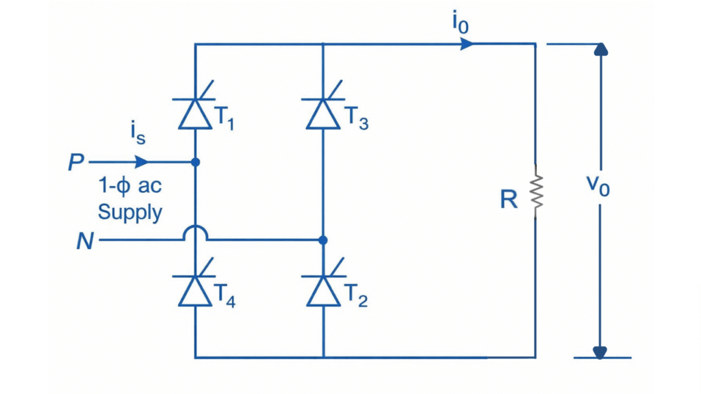
Single Phase Fully Controlled Bridge Rectifier with R Load
Operation
During Positive Half Cycle (α <ωt< π)
In the positive half cycle, thyristors T1 and T2 are forward biased and conduct when triggered at firing angle α. Current flows through T1 → R load → T2, producing a positive output voltage across the load. Since the load is resistive, current follows the voltage and becomes zero at the end of the half cycle.
During Negative Half Cycle (π+α <ωt< 2π)
In the negative half cycle, thyristors T3 and T4 are forward biased and conduct when triggered at angle α. Current flows through T3 → R load → T4 in the same direction as before, giving a unidirectional output. The current again becomes zero when the input voltage crosses zero.
Output Waveform

Average Output Voltage
Where:
- = Maximum value of AC input voltage
- = Firing angle
Average Output Current
Since load is resistive:
Where:
- = Load resistance
RMS Output Voltage
RMS Output Current
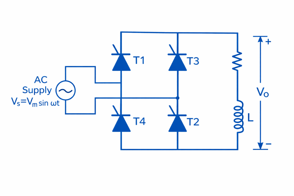
Single Phase Fully Controlled Bridge Rectifier with RL Load
Operation
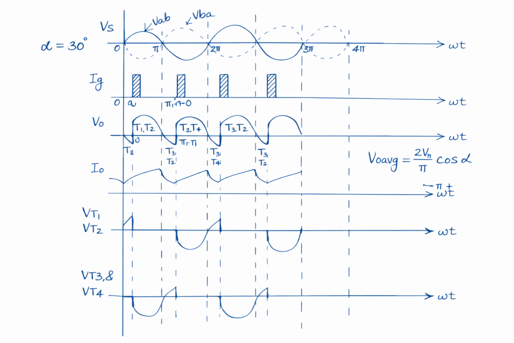
When the AC supply is applied, two thyristors conduct in each half cycle depending on the firing angle α. During the positive half cycle, thyristors T1 and T2 are forward biased and are triggered at . Current flows through T1 → R–L load → T2, producing a positive output voltage. Due to the presence of inductance, the load current does not become zero at and continues beyond this point.
In the negative half cycle, thyristors T3 and T4 are triggered at . Current now flows through T3 → R–L load → T4 while maintaining the same direction in the load. Because of the inductive load, current overlaps between successive thyristor pairs, ensuring continuous current flow. By varying the firing angle α, the average output voltage and current can be controlled.
Mode Determination
- Continuous Conduction Mode (CCM)
Occurs when the load inductance is sufficiently large:
Discontinuous Conduction Mode (DCM)
Occurs when the load inductance is small:
Output Waveform
Average Output Voltage
Average Output Current
For RL load (with continuous current):
RMS Output Voltage
RMS Output Current
Single Phase Fully Controlled Bridge Rectifier with RLE Load
In an RLE load, the circuit consists of Resistance (R), Inductance (L), and a DC source (E) (such as a battery or back-emf of a motor).
The inductance maintains current continuity, while E may oppose or assist the supply, allowing both rectification and inversion.
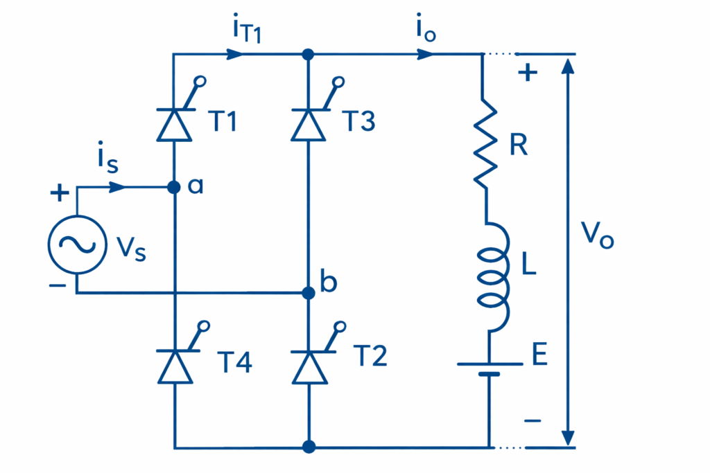
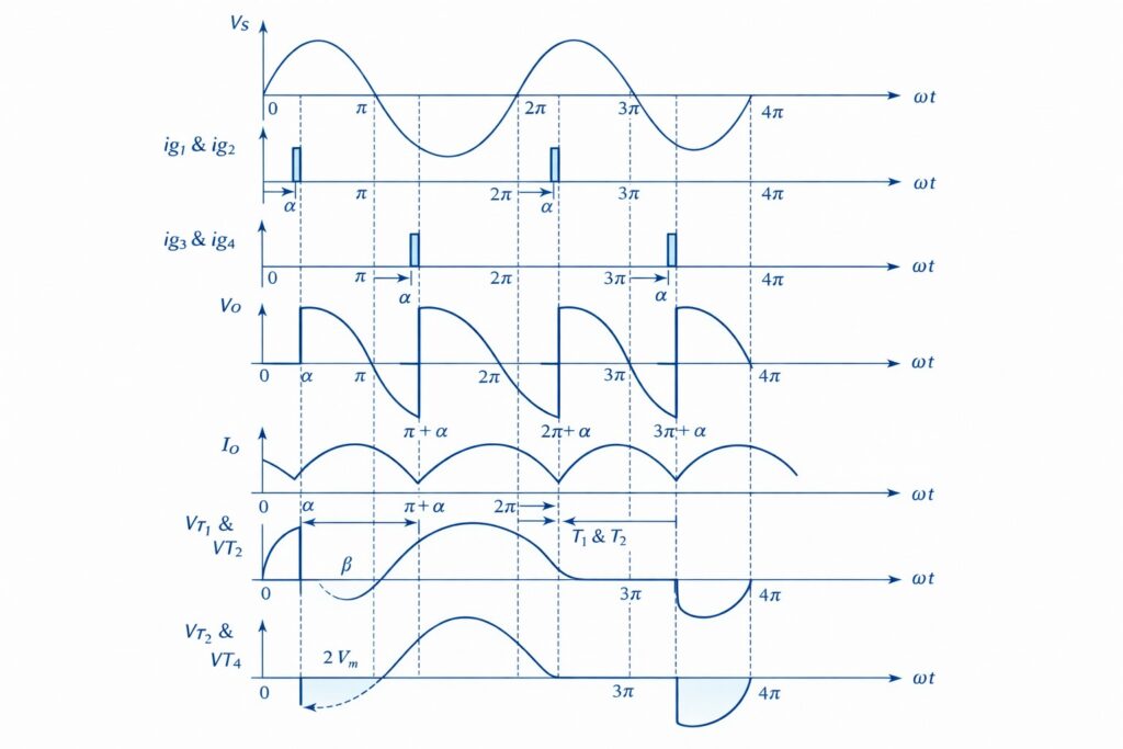
fig. 5:single phase fully controlled rectifier with rle load
Operation
Positive Half-Cycle (α <ωt< π)
- Thyristors T1 and T2 are forward-biased.
- They do not conduct until they receive a firing pulse at delay angle α.
- Once triggered, the load voltage Vo follows the supply voltage Vs.
- Energy Storage: The inductor L stores energy, which allows the current to continue flowing even after Vs drops below E or passes zero.
Negative Half Cycle (π < ωt < 2π)
- AC supply voltage is negative.
- Thyristors T3 and T4 are forward biased.
- When triggered at π + α, T3 and T4 conduct.
- Current path:
Vs → T3 → R → L → E → T4 → Vs - Load current continues in the same direction.
Modes of Operation
1. Rectification Mode (α < 90°)
- Average output voltage is positive.
- Power flows from AC source to DC load.
2. Inversion Mode (α > 90° and E present)
- Average output voltage becomes negative.
- Power flows from DC side back to AC supply (regenerative operation).
Output Waveform