
Introduction
In alternating current (AC) systems, current distribution inside conductors is not always uniform. Apart from skin effect, another important phenomenon that affects conductor performance is the Proximity Effect.
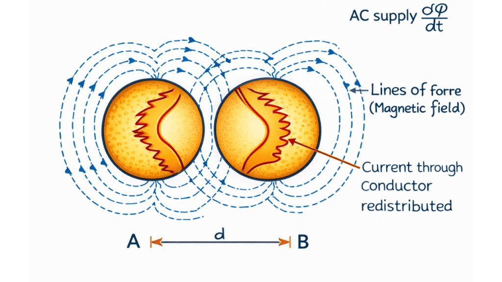
The proximity effect occurs when two or more conductors carrying AC are placed close to each other. The magnetic field produced by one conductor influences the current distribution in the neighboring conductor, leading to uneven current density, increased AC resistance, and additional power losses.
Understanding proximity effect is essential in the design of power cables, transformer windings, motor windings, bus bars, and transmission lines.
What is Proximity Effect?
Proximity effect is the tendency of alternating current to concentrate in certain regions of a conductor due to the influence of the magnetic fields produced by nearby current-carrying conductors.
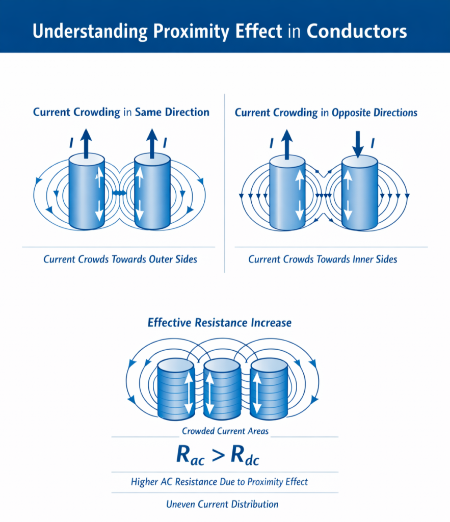
Because of this effect, current does not flow uniformly throughout the cross-section. Instead, it crowds toward particular sides of the conductor, increasing the effective resistance.
Factors Affecting Proximity Effect
The magnitude of proximity effect depends on several electrical and geometrical factors. These factors determine how strongly the magnetic fields of nearby conductors influence current distribution.
1. Frequency of Supply
Frequency is the most important factor affecting proximity effect.
As the frequency of AC increases:
- The rate of change of magnetic field increases
- Stronger eddy currents are induced in nearby conductors
- Current crowding becomes more severe
Hence:
- Higher frequency → stronger proximity effect
- At power frequency (50–60 Hz), the effect is moderate
- At high frequencies (kHz and above), the effect becomes very significant
This is why proximity effect is critical in high-frequency transformers and inductors.
2. Spacing Between Conductors
The distance between conductors greatly influences magnetic coupling.
- When conductors are placed very close, their magnetic fields strongly interact
- This induces larger eddy currents and causes heavy current crowding
- When spacing is increased, magnetic interaction weakens
Therefore:
- Smaller spacing → higher proximity effect
- Larger spacing → reduced proximity effect
Closely packed windings and bus bars suffer maximum losses due to this factor.
3. Diameter of Conductors
The size of the conductor also affects current distribution.
- In large-diameter conductors, the cross-sectional area is large
- Magnetic field variation across the conductor becomes significant
- Current tends to concentrate in limited regions
Hence:
- Larger diameter → more non-uniform current distribution → higher proximity effect
- Thin conductors show comparatively smaller proximity effect
This is why thick solid conductors are avoided in high-frequency applications.
4. Arrangement of Conductors
The physical layout and relative position of conductors plays an important role.
- Parallel conductors placed side by side produce strong mutual magnetic fields
- Closely packed coils and windings show heavy interaction
- Unsymmetrical layouts cause uneven current crowding
Thus:
- Closely packed and parallel arrangements → stronger proximity effect
- Symmetrical and properly spaced layouts reduce the effect
This factor is very important in transformer windings, motor slots, and cable groups.
5. Material of Conductor
The electrical properties of conductor material influence eddy current formation.
- High conductivity materials (such as copper and aluminium) allow larger induced currents
- These induced currents distort current distribution more severely
- Magnetic permeability of the material also affects the field pattern
Therefore:
- High conductivity materials → more pronounced proximity effect
- Low conductivity materials show comparatively smaller effect
Copper conductors, though efficient, require special design at high frequencies to reduce losses.
Reduction Methods of Proximity Effect
Since proximity effect increases AC resistance, copper losses, and heating, it is essential to minimize this effect in practical electrical systems. Several design and construction techniques are used to reduce proximity effect and improve system efficiency.
1. Increase Spacing Between Conductors
One of the simplest and most effective methods to reduce proximity effect is to increase the distance between adjacent conductors.
- Greater spacing reduces magnetic coupling between conductors
- The strength of induced eddy currents decreases
- Current distribution becomes more uniform
As a result:
- AC resistance decreases
- Power losses reduce
- Heating is minimized
This method is commonly applied in bus bars, transmission lines, and cable layouts.
2. Use Stranded Conductors Instead of Solid Conductors
Replacing a single thick solid conductor with multiple thin strands significantly reduces proximity effect.
Advantages:
- Each strand carries a smaller portion of current
- Eddy current paths are interrupted
- Magnetic field penetration becomes more uniform
This leads to:
- Improved current distribution
- Lower AC resistance
- Reduced copper losses
Stranded conductors are widely used in power cables and machine windings.
3. Use Litz Wire for High-Frequency Applications
Litz wire is the most effective solution for reducing proximity effect in high-frequency systems.
Construction:
- Consists of many thin insulated strands
- Strands are twisted and woven so that each strand occupies all possible positions
Benefits:
- Uniform current distribution in all strands
- Minimal skin effect and proximity effect
- Very low AC resistance
Applications:
- High-frequency transformers
- Inductors and chokes
- Switching power supplies
- RF circuits
4. Proper Arrangement and Symmetrical Layout of Conductors
The physical layout of conductors strongly influences proximity effect.
Design guidelines:
- Avoid tightly packed conductors
- Use symmetrical arrangements
- Maintain uniform spacing between conductors
- Avoid irregular or unsymmetrical layouts
These practices:
- Reduce unequal magnetic interaction
- Minimize current crowding
- Improve thermal performance
This method is especially important in transformer windings and motor slots.
5. Use Transposed Conductors in Transmission Lines
In overhead transmission lines, conductors are periodically transposed along the line length.
Purpose of transposition:
- Each conductor occupies different relative positions
- Magnetic influence is averaged over the entire length
- Unequal current distribution is minimized
Benefits:
- Balanced inductance and resistance
- Reduced proximity effect
- Improved voltage regulation
This technique is essential in long high-voltage transmission lines.
6. Use Hollow or Tubular Conductors for Large Currents
For very large current applications, hollow conductors are often preferred.
Reasons:
- Current mainly flows near the outer surface
- Central material is not effectively utilized
- Hollow conductors reduce unnecessary metal and losses
Advantages:
- Lower AC resistance
- Reduced heating
- Better cooling due to air circulation
Used in bus bars, furnace conductors, and high-current feeders.
7. Reduce Conductor Diameter and Increase Number of Parallel Conductors
Instead of using one thick conductor, using several smaller conductors in parallel helps reduce proximity effect.
Benefits:
- Smaller diameter reduces current crowding
- Magnetic field distribution becomes more uniform
- Lower eddy current formation
Common in:
- Power transformer windings
- High-current cables
- Motor stator windings
| Feature | Skin Effect | Proximity Effect |
|---|---|---|
| Cause | Self magnetic field | Magnetic field of nearby conductors |
| Occurs in | Single conductor | Multiple nearby conductors |
| Current crowding | Toward surface | Toward specific sides |
| Depends on spacing | No | Yes |

1 thought on “Proximity Effect – Affecting Factors & Reduction Methods”
Great content!