Introduction
The polarity test of a transformer is carried out to determine the relative polarity of the primary and secondary windings. It shows whether the induced voltages in both windings are in phase or out of phase with each other.
This test is extremely important before making series or parallel connections of transformers.
What is Polarity of a Transformer?
In a two-winding transformer, one terminal of each winding becomes positive with respect to the other terminal at a given instant.
The polarity of a transformer indicates the relative direction of the induced voltages in the high-voltage (HV) and low-voltage (LV) windings.
In practice, polarity depends on how the leads are brought out from the transformer windings.
Types of Polarity of a Transformer
The polarity of a transformer is classified into two types:
- Additive polarity
- Subtractive polarity
Let,
- = primary voltage
- = secondary voltage
- = voltmeter reading across the free terminals
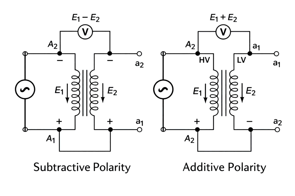
Depending on the connection, the voltmeter reading will be either the sum or the difference of the two voltages.
Additive Polarity
In additive polarity, the voltmeter reads the sum of the primary and secondary voltages.
This indicates that the induced voltages of both windings are in the same direction at the connected terminals.
Subtractive Polarity
In subtractive polarity, the voltmeter reads the difference of the primary and secondary voltages.
This indicates that the induced voltages of both windings are in opposite directions at the connected terminals.
Video credit: TechInsight
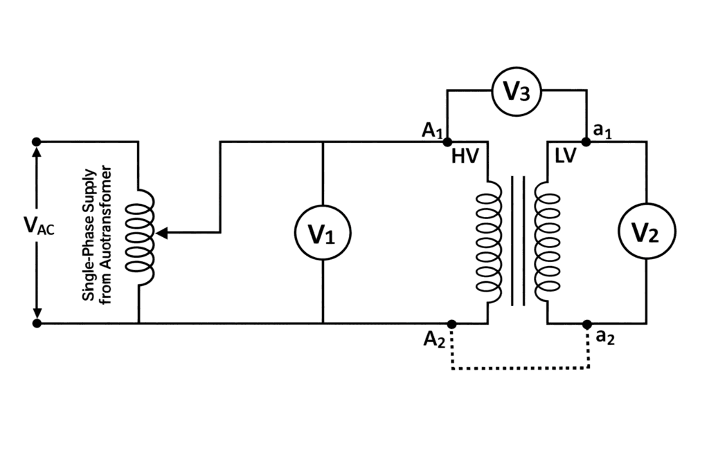
Practicle Circuit Diagram
Additive Polarity
Subtractive Polarity
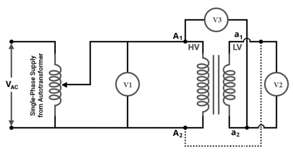
Test Procedure
- Apply a low AC voltage to the primary winding.
- Connect one terminal of the primary winding to one terminal of the secondary winding.
- Measure the primary voltage , secondary voltage , and combined voltage .
- Compare the readings.
- If , the transformer has additive polarity.
- If , the transformer has subtractive polarity.
Importance of Polarity Test
The polarity test is very important because:
- it ensures correct series and parallel connection of transformers,
- it avoids circulating currents,
- and it prevents short-circuit during parallel operatio
Conclusion
The polarity test of a transformer is a simple and essential test used to identify whether the primary and secondary induced voltages are additive or subtractive. It ensures correct terminal identification and is especially important before parallel operation and protection system connections.
Related Posts: