What is Open Circuit and Short Circuit Test?
The open-circuit test and short-circuit test are used to determine the losses and equivalent circuit parameters of a transformer. These tests are simple and economical, and they are performed without loading the transformer.
- The open-circuit test is carried out to find the core losses and no-load parameters.
- The short-circuit test is used to determine the copper losses and series parameters.
Using the results of these tests, efficiency and voltage regulation of the transformer can be evaluated accurately.
Open Circuit Test on Transformer (No-Load Test)
The open-circuit test, also known as the no-load test, is performed on a transformer to determine its core losses and shunt parameters of the equivalent circuit. This test is carried out without loading the transformer, making it simple and economical.
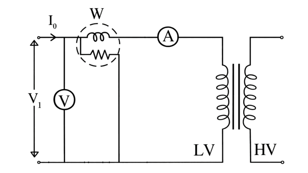
In this test low voltage winding (primary) is connected to a supply of normal voltage and frequency (as per the rating of transformer) and the high voltage winding (secondary) is left open as shown in fig.
The primary winding draws very low current hardly 3 to 5 percentage of full load current (may be upto 10% for very small rating transformer used for laboratory purpose) under this condition. As such copper losses in the primary winding will be negligible. Thus mainly iron losses occur in the transformer under no load or open circuit condition, which are indicated by the wattmeter connected in the circuit.
Hence, total iron losses = W₀ (Reading of Wattmeter)
From the observation of this test, the parameters R₀ and Xₘ of the parallel branch of the equivalent circuit can also be calculated, following the steps given below :
Power drawn, W₀ = V₀ I₀ cos φ₀
Thus, no load power factor, cos φ₀ =
Core loss component of no load current, I_w = I₀ cos φ₀
And, magnetising component of no load current, I_m = I₀ sin φ₀
Equivalent resistance representing the core loss, R₀ =
Magnetising reactance representing the magnetising current, X₀ =
Short-Circuit Test on Transformer (Impedance Test)
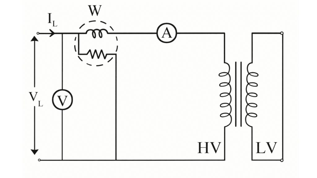
Short-Circuit Test Connection
In this test, low voltage winding is short circuited and a low voltage hardly 5 to 8 percent of the rated voltage of the high voltage winding is applied to this winding. This test is performed at rated current flowing in both the windings. Iron losses occurring in the transformer under this condition is negligible, because of very low applied voltage.
Hence the total losses occurring under short cvv circuit are mainly the copper losses of both the winding, which are indicated by the wattmeter connected in the circuit as shown in fig.
Thus total full load copper losses = (reading of wattmeter)
The equivalent resistance and reactance referred to a particular winding can also be calculated from the observation of this test, following the steps given below.
Equivalent resistance referred to H.V. winding,
Also, equivalent impedance referred to H.V. winding,
Thus the equivalent reactance referred to H.V. winding,
Video credit: ELECTRICAL VEDA
PERFORMANCE CALCULATIONS :
Complete performance of the transformer can be calculated based on the above observation of open-circuit and short-circuit test following the steps given by,
1. Efficiency at different loads :
(a) Efficiency at full load :
Total losses at full load =
Let the full load output power of the transformer in KVA be
Then percentage efficiency at full load,
(b) Efficiency at half the full load :
Iron losses at half the full load = (constant)
Total copper losses at half the full load =
Output power at half full load =
Thus, percentage efficiency at half the full load,
In a similar manner, efficiency at other loads can be found out and the efficiency Vs output power curve can be plotted.
2. Equivalent circuit :
All the parameters of the approximate equivalent circuit has been calculated above. Thus an approximate equivalent circuit of the transformer can be drawn with these value of parameters marked on it. The equivalent circuit can be solved easily for estimating the performance like terminal voltage across the secondary etc.
3. Regulation :
Regulation of the transformer can now be calculated based on the parameters of the equivalent circuit, using the approximate formula given below.
Where,
I – rated current of the winding referred to which and have been calculated.
V – Voltage of that winding.
Cos φ – Power factor at which regulation is to be calculated.
Conclusion
The open-circuit and short-circuit tests are used to determine transformer parameters required for evaluating efficiency and voltage regulation. Both tests have been explained separately in this article with clear descriptions and examples.
Related Posts:
Sumpner’s Test (Back-to-Back) on Transformer
Polarity Test of a Transformer