Introduction to Magnetic Circuits
A magnetic circuit is the closed path followed by magnetic flux.
In electrical machines and transformers, magnetic circuits are formed using ferromagnetic materials such as iron or silicon steel because these materials provide a low-reluctance path for magnetic flux.
In most practical machines, the magnetic field is produced by passing electric current through coils wound on a magnetic core. Unlike permanent-magnet machines, the flux in conventional machines is created by current-carrying conductors.
Current and Magnetic Field Intensity (I–H Relation)
We shall first study how the current in a coil is related to the magnetic field intensity (or magnetic flux) it produces. When a conductor carries current, a magnetic field is produced around it, as illustrated in the figure of a straight current-carrying conductor. The direction of the flux lines or magnetic field intensity H can be determined by the right-hand thumb rule. According to this rule, if the conductor is held in the right hand with the thumb pointing in the direction of current, the curled fingers indicate the direction of the magnetic field intensity.
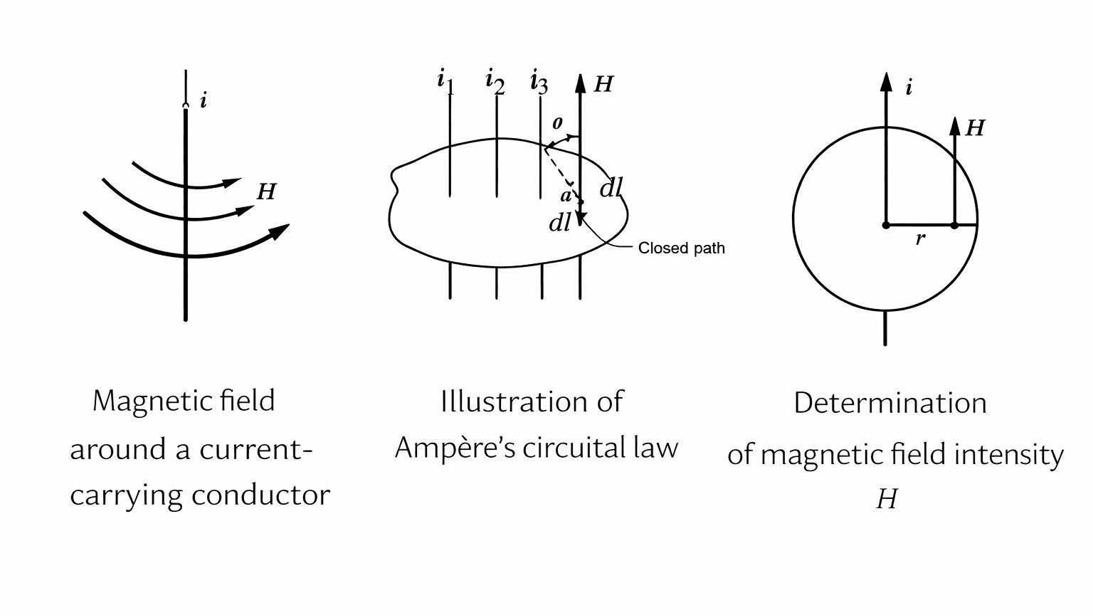
The relationship between current and magnetic field intensity is obtained using Ampere’s circuital law, which states that the line integral of the magnetic field intensity H around a closed path is equal to the algebraic sum of the currents enclosed by that path.
where H is the magnetic field intensity at a point on the contour and dl is the incremental length element along the contour. If θ is the angle between the vectors H and dl, the above relation can be written as
Now consider a straight conductor carrying a steady current i. To obtain an expression for the magnetic field intensity H at a distance r from the conductor, an imaginary circular path of radius r is drawn around the conductor. At every point on this circular contour, the directions of H and dl are the same, and therefore θ = 0. Due to symmetry, the magnitude of H is constant over the entire circular path. Hence,
Since the length of the circular path is
Therefore, the magnetic field intensity at a distance r from a straight current-carrying conductor is
This expression shows that the magnetic field intensity produced by a straight conductor is directly proportional to the current and inversely proportional to the radial distance from the conductor.
Magnetic Flux Density and Field Intensity (B–H Relation)
Figure shows a simple magnetic circuit having a ring-shaped magnetic core, called a toroid, and a coil that extends around the entire circumference.
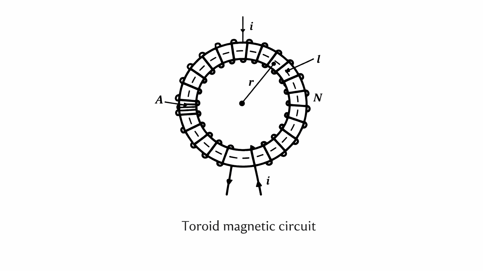
When a current i flows through a coil of N turns, the magnetic flux is mainly confined within the core material. The flux outside the toroid, known as leakage flux, is very small and can be neglected for practical purposes.
Consider a circular magnetic path of mean length l inside the toroid. The magnetic field intensity along this path is H. From Ampere’s circuital law,
Since the magnetic field is assumed uniform along the path,
For a toroid of mean radius r, the magnetic path length is , hence
The quantity Ni is called the magnetomotive force (mmf) and is denoted by F. Its unit is ampere-turn.
Therefore,
Using the relation between flux density and field intensity,
the flux density in the toroidal core becomes
If all the magnetic flux is assumed to be confined within the toroid and leakage is neglected, the total magnetic flux crossing the cross-section of the core is
For uniform flux density over the cross-sectional area A,
Substituting for B,
This expression may also be written in the form
where the magnetic reluctance of the toroidal path is
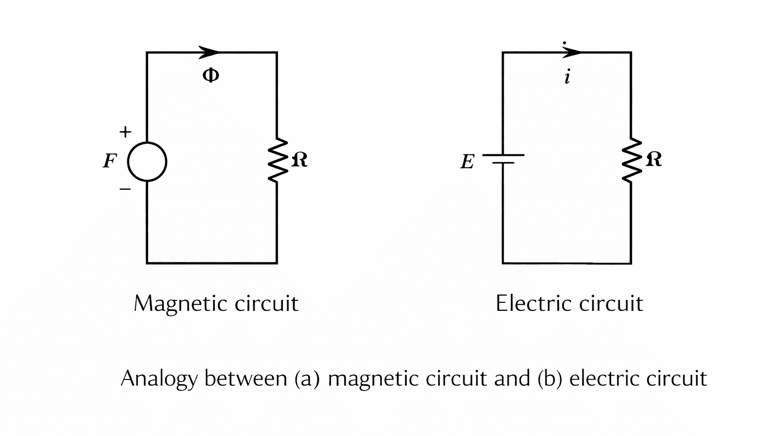
Analogy Between Electrical and Magnetic Circuits
| Electrical Circuit | Magnetic Circuit |
|---|---|
| EMF (E) | MMF (F) |
| Current (I) | Flux |
| Resistance (R) | Reluctance |
| Conductivity | Permeability |
Reluctance is the opposition offered by a magnetic path to the establishment of magnetic flux. It depends on the length of the magnetic path, the cross-sectional area of the path and the permeability of the material. A longer magnetic path and a smaller cross-section increase the reluctance, while a higher permeability reduces it.
The reciprocal of reluctance is called permeance, which indicates how easily magnetic flux can pass through the magnetic path.
In a magnetic circuit, the driving force that produces magnetic flux is called the magnetomotive force. It is produced by the current flowing through a coil and is equal to the product of the number of turns and the current. This magnetomotive force drives the magnetic flux through the magnetic path against the opposition offered by reluctance.
Hence, the magnetic circuit can be expressed in a form similar to an electric circuit as
where
Here,
is the magnetic flux,
is the magnetomotive force,
is the reluctance of the magnetic path,
is the permeance,
is the mean length of the magnetic path,
is the cross-sectional area, and
is the permeability of the material.
Magnetization Curve
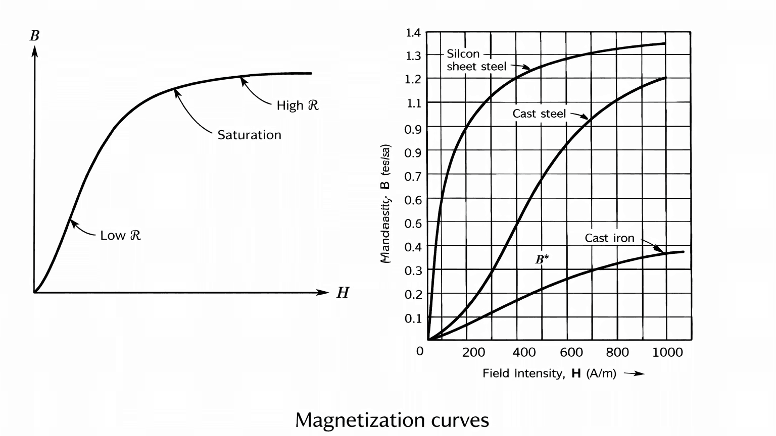
If the magnetic field intensity in the core is increased by increasing the current, the flux density in the core changes as shown by the magnetization characteristic. The flux density B increases almost linearly in the region of low values of magnetic field intensity H. However, at higher values of H, the change of B is nonlinear. The magnetic material shows the effect of saturation.
The B–H curve is called the magnetization curve. The reluctance of the magnetic path depends on the flux density. It is low when B is low and high when B is high.
The B–H characteristics of three different magnetic materials cast iron, cast steel and silicon sheet steel show that, in order to establish the same level of flux density in different magnetic materials, the required current is different.
Expressions used for the magnetization curve
The basic relation between flux density and magnetic field intensity is
where
- is the magnetic flux density,
- is the magnetic field intensity, and
- is the permeability of the material.
Since the permeability of ferromagnetic materials varies with the magnetic field intensity, it can be written as
This shows that permeability is not constant and changes with the operating point on the magnetization curve.
The reluctance of the magnetic path is given by
Because varies with the value of , the reluctance of a magnetic circuit also varies with the flux density.
Magnetic Circuit with Air Gap
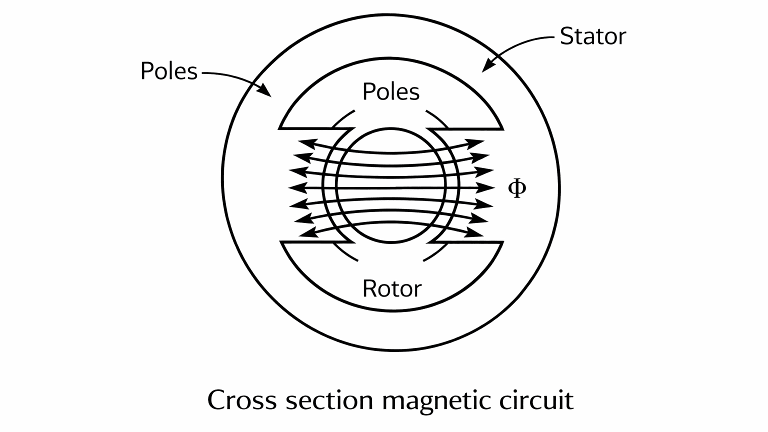
In practical electric machines, the magnetic path is not made of a single material. The rotor and stator are separated by a small air gap, so the magnetic flux must pass through both the iron core and the air. Even though almost the same magnetic flux flows through the core and the air gap, the air gap requires a much larger magnetomotive force because air has very low permeability compared to iron.
When the operating flux density becomes high, the iron part of the magnetic circuit may enter saturation. This means that further increase in current produces only a small increase in flux. The air gap, however, does not saturate, because the magnetic characteristic of air is linear and its permeability remains practically constant.
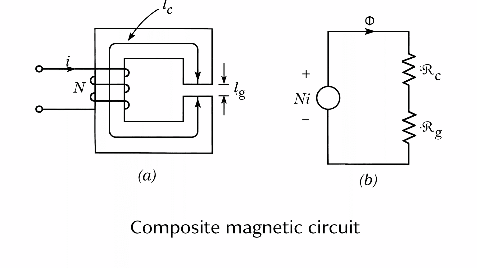
A magnetic circuit that contains more than one medium, such as an iron core and an air gap, is called a composite magnetic circuit. For analysis, this composite structure can be represented by an equivalent magnetic circuit in which each part of the magnetic path is replaced by its own reluctance.
In this type of circuit, the driving force is the magnetomotive force produced by the exciting coil. The core and the air gap oppose the flux by their individual reluctances, and these reluctances act in series. Therefore, the same flux flows through both the core and the air gap, but the total opposition to flux is the sum of their individual oppositions.
The behaviour of the composite magnetic circuit can be expressed using the following relations:
The flux densities in the core and in the air gap are given by
In the air gap, the magnetic flux lines spread out slightly near the edges instead of remaining perfectly straight. This spreading of flux is known as fringing. Fringing effectively increases the cross-sectional area of the air gap and slightly reduces its effective reluctance.
The effect of the fringing is to increase the cross-sectional area of the air gap. For small air gaps the fringing effect can be neglected. If the fringing effect is neglected, the cross-sectional areas of the core and the air gap are the same.