The extensive use of power-electronic converters in modern industrial, commercial, and utility networks has significantly transformed the operating characteristics of electrical power systems. While these technologies improve controllability, efficiency, and flexibility, they also introduce new power-quality challenges. Consequently, maintaining acceptable levels of power quality, together with improved energy efficiency, has become a major technical and economic concern for utilities, energy managers, and plant engineers.
Among the various power-quality phenomena, harmonic distortion is one of the most critical indicators. It represents the deviation of practical voltage and current waveforms from their ideal sinusoidal form, mainly caused by non-linear loads such as rectifiers, variable-speed drives, inverters, and modern electronic equipment. The increasing penetration of such loads has made harmonic analysis and mitigation an essential part of electrical system design and operation.
Harmonic distortion can lead to higher system losses, abnormal operation of equipment, interference with sensitive electronic devices, and reduced reliability of electrical installations. For this reason, internationally recognized guidelines and limits for harmonic emission and assessment are defined by organizations such as the Institute of Electrical and Electronics Engineers and the International Electrotechnical Commission. These standards provide the technical framework for evaluating harmonic levels and ensuring acceptable power quality in modern electrical networks.
What are harmonics?
Harmonics are sinusoidal components of voltage or current whose frequencies are integer multiples of the fundamental frequency and which arise mainly due to non-linear loads, causing distortion of the electrical waveform.
If the fundamental frequency is (50 Hz in most countries including India), then the harmonic frequencies are:
Hence, harmonics are additional frequency components that appear along with the fundamental component and distort the waveform.In an ideal system, both voltage and current should be perfectly sinusoidal. In practice, due to non-linear loads, the waveform becomes distorted because of harmonics.
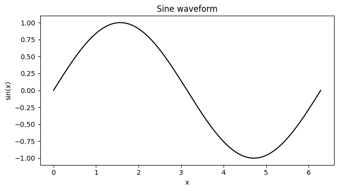
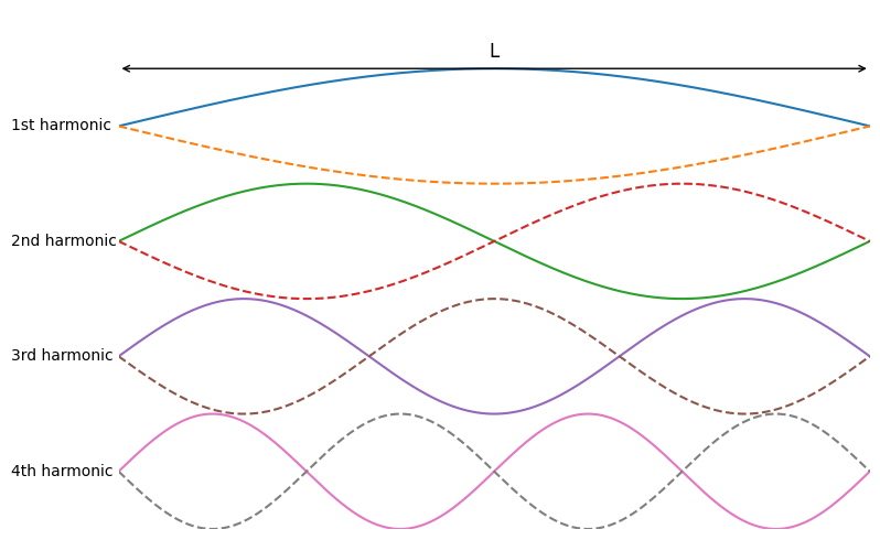
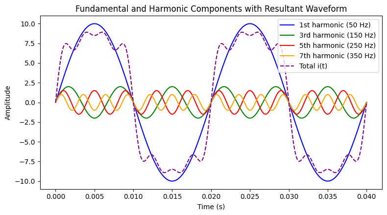
The figures illustrates how a distorted waveform is formed by the superposition of a fundamental sinusoidal component and one or more harmonic components. The smooth sinusoidal curve represents the fundamental component, while the higher-frequency oscillations correspond to harmonic components. When these components are added together, the resulting waveform deviates from a pure sine wave, producing the distorted voltage or current observed in practical power systems.
Mathematical Representation
The harmonic frequency is given by
Any periodic sinusoids can be expressed as sum of sinusoids. When a waveform is identical from one cycle to the next, it can be represented as a sum of pure sine waves in which the frequency of each sinusoid is an integer multiple of the fundamental frequency of the distorted wave. Harmonics is the integer multiple of fundamental component.
A distorted current (or voltage) waveform can be expressed as the sum of the fundamental and its harmonic components as
where,
- is the instantaneous current (or voltage),
- is the amplitude of the fundamental component,
- are the amplitudes of the harmonic components, and
- is the angular frequency of the fundamental component.
Harmonic order and frequency
For a 50 Hz power system, the relationship between harmonic order and frequency is shown in the table below.
| Harmonic order (h) | Component name | Frequency (Hz) |
|---|---|---|
| 1 | Fundamental | 50 |
| 2 | 2nd harmonic | 100 |
| 3 | 3rd harmonic | 150 |
| 4 | 4th harmonic | 200 |
| 5 | 5th harmonic | 250 |
| 7 | 7th harmonic | 350 |
| 11 | 11th harmonic | 550 |
| 13 | 13th harmonic | 650 |
Harmonics, which are nothing but distorted waveforms, have two types, namely voltage harmonics and current harmonics. The orders of harmonics and symmetrical components are two concepts that are commonly used to describe harmonics. Regarding harmonics, the terms odd harmonics and even harmonics are usually used, but the term triplen harmonics is not very commonly known.
| Category | Harmonic orders |
|---|---|
| Odd harmonics | 5th, 7th, 11th, 13th, 17th |
| Even harmonics | 2nd, 4th, 6th, 8th, 10th, 12th |
| Triplen harmonics | 3rd, 9th, 15th, 21st |
How harmonics are generated in system
Ideal (linear load) condition
When a linear load, such as a pure resistive load or an induction heater, is connected to a sinusoidal voltage supply, the current drawn by the load is also sinusoidal and follows the same waveform as the applied voltage. In this case, the current is directly proportional to the voltage, and therefore no harmonic components are generated.
Non-linear load condition
Non-linear loads are the main source of harmonics in practical electrical systems. Most modern equipment uses power-electronic devices such as diodes, thyristors, MOSFETs and IGBTs, and these types of loads are therefore classified as non-linear loads. A non-linear load is one in which the current drawn is not proportional to the applied voltage. As a result, even when the supply voltage is sinusoidal, the load draws a distorted and non-sinusoidal current, which leads to the generation of harmonics.
Typical examples of non-linear loads include rectifiers, inverters and variable-frequency drives (VFDs), electric-vehicle chargers, and switch-mode power supplies (SMPS).
Actual Generation Process of Harmonics (Step-by-Step)
Causes of Harmonics
The main causes of harmonics in an electrical system are:
- Non-linear loads
Loads in which current is not proportional to the applied voltage are the primary source of harmonics. - Use of power-electronic devices
Equipment using diodes, thyristors, MOSFETs and IGBTs draws current in pulses instead of a smooth sinusoidal form. - Rectifiers and converters
AC–DC and DC–AC converters (such as rectifiers and inverters) generate non-sinusoidal input currents. - Variable Frequency Drives (VFDs)
The switching operation of VFDs introduces characteristic harmonic currents into the supply. - Switch-mode power supplies (SMPS)
These supplies draw short, high-peak currents during capacitor charging, producing strong harmonics. - EV chargers and modern electronic equipment
Their internal converters and control circuits contribute significant harmonic distortion.
Effects of harmonics
- High voltages and circulating currents caused by harmonic resonance
- Equipment malfunctions due to excessive voltage distortion
- Increased internal energy losses in connected equipment, causing component failure
and shortened life span - False tripping of branch circuit breakers
- Metering errors
- Fires in wiring and distribution systems
- Generator failures
- Crest factors and related problems
- Lower system power factor, resulting in penalties on monthly utility bills
Reduction Techniques of Harmonics
The most commonly used techniques for reducing harmonics in electrical power systems are:
- Passive harmonic filters
LC tuned filters are connected to the system to provide a low-impedance path for selected harmonic orders, thereby removing specific harmonics from the network. - Active power filters (APF)
Active filters measure the harmonic current and inject an equal and opposite compensating current, effectively cancelling the harmonic components in real time. - Multi-pulse converter arrangements
Using 12-pulse, 18-pulse or higher-pulse rectifiers significantly reduces characteristic harmonics at the source by phase-shifting transformer connections. - Detuned capacitor banks
Capacitor banks are combined with series reactors to avoid resonance with system harmonics and to limit harmonic amplification. - Proper system design and load segregation
Separating sensitive loads, selecting suitable transformer connections, and placing non-linear loads appropriately help in limiting the spread of harmonic distortion. - Use of low-harmonic or active front-end converters
Modern converters with PWM control and active front ends draw nearly sinusoidal input current, thereby reducing harmonic generation at the source.
In practice, the most effective approach is to combine source-level solutions (low-harmonic equipment and multi-pulse converters) with network-level solutions (filters and detuned capacitor banks).