Introduction
A dual converter is a power electronic system formed by connecting two fully controlled bridge converters (thyristor bridges) in anti-parallel configuration across a common DC load. It allows reversible DC voltage and current, making it suitable for four-quadrant operation.
Dual converters are widely used in reversible DC motor drives, where smooth and fast control of speed and direction is required.
Basic Circuit Configuration
A dual converter consists of:
- Converter-1 (Positive group) → produces positive DC voltage
- Converter-2 (Negative group) → produces negative DC voltage
- Both converters are supplied from the same AC source
- Output terminals are connected in anti-parallel
Only one converter actively supplies power at a time (or both in circulating current mode).
Modes of Operation of Dual Converter
There are two functional modes:
- Non-circulating current mode
- circulating current mode
Non Circulating Current Mode
- One converter will perform at a time. So there is no circulating current between the converters.
- During the converter 1 operation, firing angle (α1) will be ; Vdc and Idc are positive.
- During the converter 2 operation, firing angle (α2) will be and both and are negative.
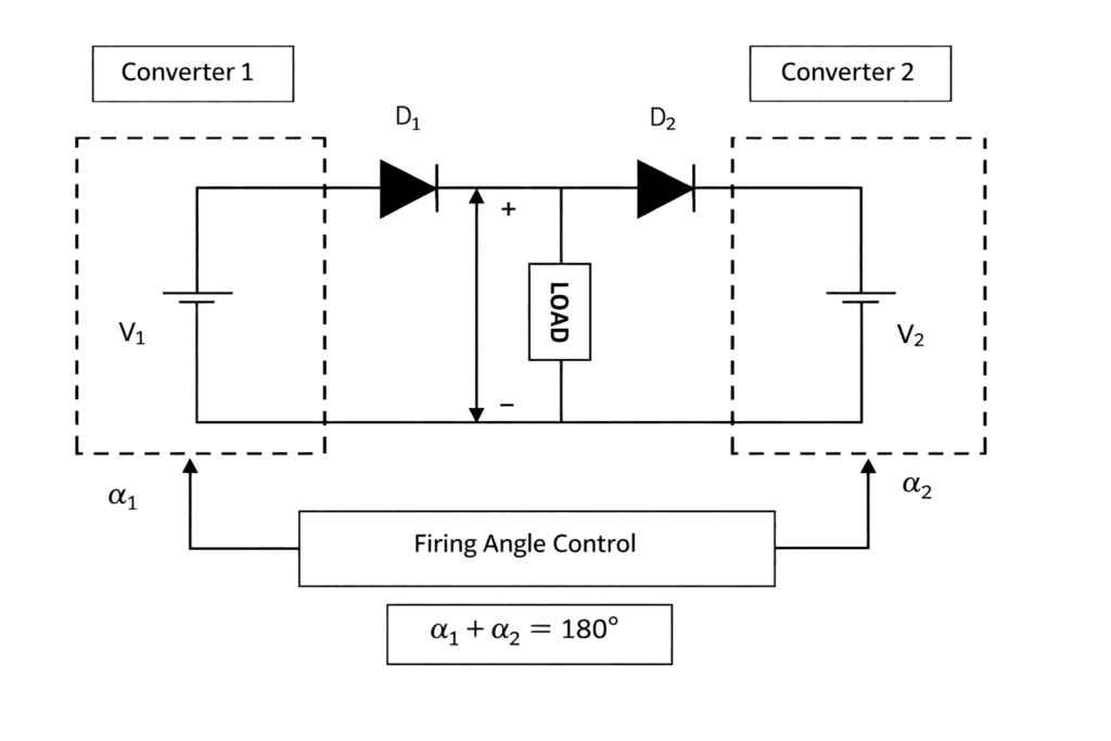
Circulating Current Mode
- Two converters will be in the ON condition at the same time. So circulating current is present.
- The firing angles are adjusted such that firing angle of converter 1 (α₁) + firing angle of converter 2 (α₂) = 180°.
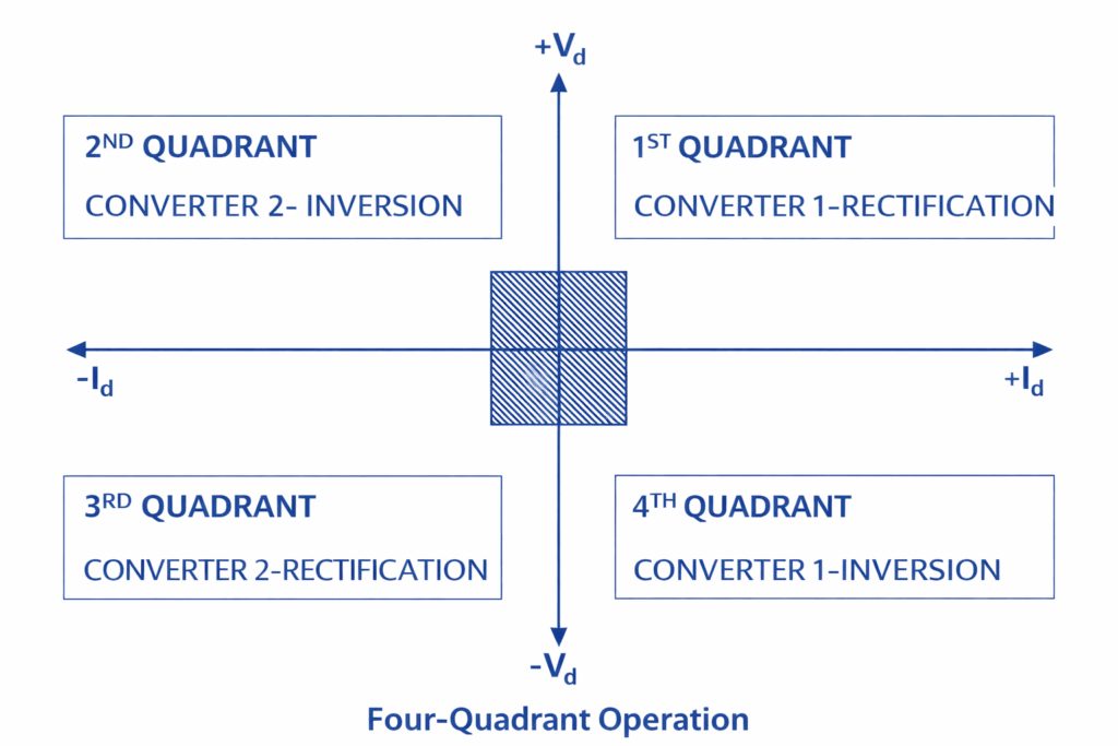
- Converter 1 performs as a controlled rectifier when firing angle be 0 < α₁ < 90° and Converter 2 performs as an inverter when the firing angle be 90° < α₂ < 180°. In this condition, Vdc and Idc are positive.
- Converter 1 performs as an inverter when firing angle be 90° < α₁ < 180° and Converter 2 performs as a controlled rectifier when the firing angle be 0 < α₂ < 90°. In this condition, Vdc and Idc are negative.
- The four quadrant operation is shown below.
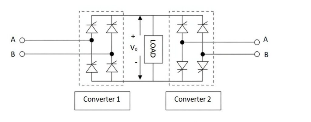
Single Phase Dual Converter
The source of this type of converter will be single-phase supply. Consider, the converter is in noncirculating mode of operation. The input is given to the converter 1 which converts the AC to DC by the method of rectification. It is then given to the load after filtering. Then, this DC is provided to the converter 2 as input. This converter performs as inverter and converts this DC to AC. Thus, we get AC as output. The circuit diagram is shown below.
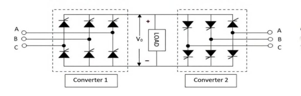
Three Phase Dual Converter
Here, three-phase rectifier and three-phase inverter are used. The processes are similar to single-phase dual converter. The three-phase rectifier will do the conversion of the three-phase AC supply to the DC. This DC is filtered and given to the input of the second converter. It will do the DC to AC conversion and the output that we get is the three-phase AC. Applications where the output is up to 2 megawatts. The circuit is shown below.
Applications of Dual Converter
- Direction and speed control of DC motors, providing smooth and rapid reversal of rotation.
- Used in systems where reversible DC voltage and current are required.
- Widely applied in industrial variable-speed DC drive system