Introduction
A TRIAC (Triode for Alternating Current) is a bidirectional thyristor used for controlling AC power in both positive and negative half cycles. However, a TRIAC cannot turn ON automatically; it requires a gate triggering pulse at a desired firing angle.
To obtain symmetrical, reliable, and sharp triggering pulses, a DIAC (Diode for Alternating Current) is commonly used as a triggering device for the TRIAC.
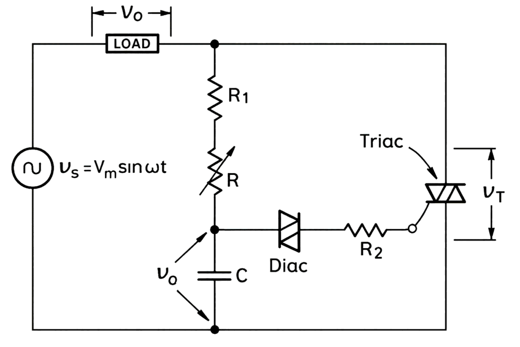
Fig. 1 shows a TRIAC firing circuit employing a DIAC. In this circuit, the resistor R is variable, whereas resistor R₁ has a fixed resistance.
When R = 0, the resistor R₁ protects the DIAC and the TRIAC gate from being exposed to almost the full supply voltage. The resistor R₂ limits the current flowing through the DIAC and the TRIAC gate when the DIAC conducts. The values of the capacitor C and the potentiometer R are selected so as to obtain a firing angle range close to 0° to 180°. However, in practice, a triggering angle range of approximately 10° to 170° is achievable using the firing circuit shown in Fig. 1.
Working of the Circuit
The variable resistor R controls the charging time of the capacitor C and hence determines the firing angle of the TRIAC. The charging time constant of the circuit is given by:
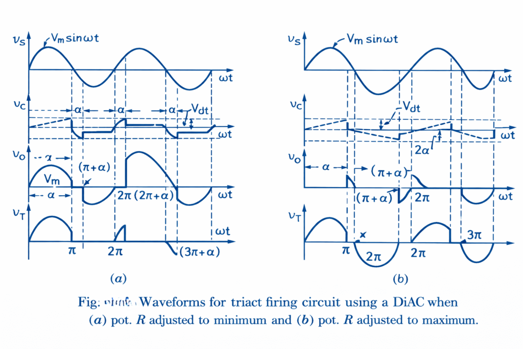
When R is small, the time constant is small, and therefore the capacitor charges rapidly. As a result, the capacitor voltage reaches the DIAC breakover voltage Vₐ earlier, causing the TRIAC to fire at a small firing angle (α).
Conversely, when R is large, the charging time increases, the DIAC fires later, and hence the firing angle of the TRIAC increases.
Positive Half Cycle Operation
During the positive half cycle of the supply voltage, the capacitor C charges with its upper plate positive. When the capacitor voltage reaches the DIAC breakdown voltage Vₐ, the DIAC turns ON. Consequently, the capacitor discharges rapidly through the DIAC and the gate circuit, producing a sharp voltage pulse across the TRIAC gate. This pulse turns the TRIAC ON at a firing angle α.
After the TRIAC turns ON, the source voltage appears across the load for a conduction interval of (π − α) radians. When the supply voltage becomes zero at ωt = π, the TRIAC turns OFF.
Negative Half Cycle Operation
After ωt = π, the supply voltage becomes negative, and the capacitor C charges again but with its lower plate positive. When the capacitor voltage reaches the negative breakover voltage of the DIAC, the DIAC conducts once more, triggering the TRIAC in the negative half cycle. The TRIAC conducts for (π − α) radians during this half cycle and turns OFF again at ωt = 2π. This process repeats continuously for successive cycles.
Waveform
Applications
- Lamp dimmers
- Heat controllers
- Fan speed regulators
Conclusion
Using a DIAC as a triggering device for a TRIAC ensures reliable, symmetrical, and efficient AC power control. The DIAC-based triggering circuit is widely preferred due to its simplicity, effectiveness, and improved waveform quality, making it a standard choice in phase-controlled AC applications.