What is DC Motor?
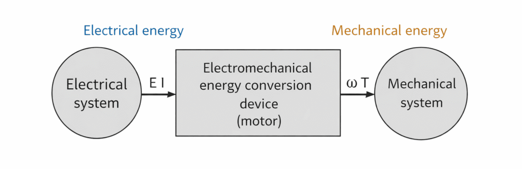
A DC motor is an electrical machine that converts direct current electrical energy into mechanical energy. It works on a very basic principle. Whenever a current carrying conductor is placed in a magnetic field, a force acts on it. The direction of this force is given by Fleming left hand rule. Because of this force, the armature starts rotating.
Working Principle
Faraday’s Laws of Electro magnetic Induction
Whenever a conductor cuts the flux of a magnetic field, an emf produced in the conductor. If the two ends of the conductor are connected to an outside circuit, the induced emf causes current to flow in the circuit.
Fleming’s right hand rule
The direction of induced current is given by Fleming’s right hand rule.
Construction of DC Motor
The construction of a DC motor is simple and strong. It mainly consists of two parts, the stator and the rotor. The stator is the stationary part that produces the magnetic field, while the rotor is the rotating part that produces mechanical output.
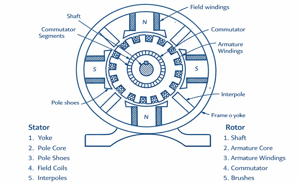
1. Stator
The stator forms the outer structure of the motor and carries the field system.
Yoke: The yoke is the outer frame of the motor. It is made of cast iron or steel. It provides mechanical support and also acts as a path for magnetic flux.
Pole Core: Pole cores are fixed inside the yoke. They support the field windings and help in producing the magnetic field.
Pole Shoes: Pole shoes are attached to the pole cores. They spread the magnetic flux uniformly over the armature surface and reduce magnetic reluctance.
Field Windings: Field windings are copper coils wound around the pole cores. When current flows through these windings, a magnetic field is produced.
Interpoles: Interpoles are small auxiliary poles placed between the main poles. They improve commutation and reduce sparking at the brushes.
2. Rotor or Armature
The rotor is mounted on a shaft and rotates inside the magnetic field.
Armature Core: The armature core is cylindrical and made of laminated silicon steel sheets. Laminations reduce eddy current losses. Slots are provided on the surface to place the armature winding.
Armature Winding: The armature winding consists of insulated copper conductors placed in the slots of the armature core. These conductors carry current and interact with the magnetic field to produce torque.
Commutator: The commutator is made of copper segments insulated from each other by mica. It is mounted on the shaft. It converts the alternating current induced in the armature into direct current and ensures unidirectional torque.
Brushes: Brushes are usually made of carbon. They press against the commutator segments and supply current to the rotating armature.
Shaft: The shaft is a steel rod connected to the armature core. It transfers mechanical energy to the external load.
Air Gap: A small air gap is maintained between the stator and rotor. It allows smooth rotation and proper magnetic flux distribution.
Working of DC Motor
A DC motor works on the principle that when a current carrying conductor is placed in a magnetic field, it experiences a mechanical force. When DC supply is given to the motor, current flows through the field winding and produces a magnetic field between the poles. At the same time, current also flows through the armature conductors through brushes and commutator. The armature conductors are placed inside the magnetic field, so they experience a force according to Fleming left hand rule.
Forces acting on opposite sides of the armature are in opposite directions, forming a couple that produces torque and causes the armature to rotate. As the armature rotates, the commutator reverses the direction of current in the conductors at the correct time, so the torque always acts in the same direction and continuous rotation is obtained. During rotation, the armature also generates an induced voltage called back EMF, which opposes the supply voltage and controls the armature current automatically.
Types of DC Motor
DC motors are mainly classified based on how the field winding is connected with the armature.
There are primarily two types of DC generators, namely,
- Separately Excited DC Motor
2. Self-Excited DC Motor
- Series DC Motor
- Series DC Motor
- Compound DC Motor
Separately Excited DC Motor
A separately excited DC motor is a type of DC motor in which the field winding is supplied from an independent external DC source, separate from the armature supply. This means the field current and armature current are controlled independently.
Applications: Rolling mills, Paper mills, Elevators, Electric traction systems, Laboratory testing machines
Self Excited DC Motor
A self excited DC motor is a type of DC motor in which the field winding gets its supply from the same source that supplies the armature. In other words, the motor does not need a separate external supply for the field winding. The field is energized using the motor’s own input supply.
Series DC Motor
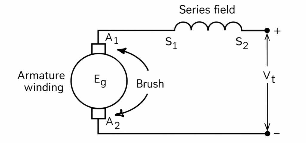
A series DC motor is a type of DC motor in which the field winding is connected in series with the armature winding. Because of this, the same current flows through both the field and the armature. This motor is known for its very high starting torque.
Applications: electric traction, cranes, hoists, elevators.
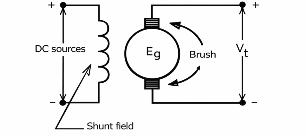
Shunt DC Motor
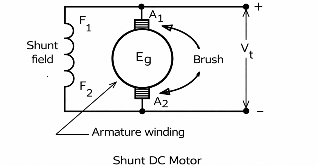
A shunt DC motor is a type of DC motor in which the field winding is connected in parallel with the armature winding. Because the field is directly across the supply, the field current remains almost constant.This motor is known for its nearly constant speed.
Applications: lathes, fans, blowers, conveyors.
Compound DC Motor
A compound DC motor is a type of DC motor that has both a series field winding and a shunt field winding. Because it uses two field windings, it combines the advantages of both series and shunt motors. It gives high starting torque like a series motor and better speed regulation like a shunt motor.
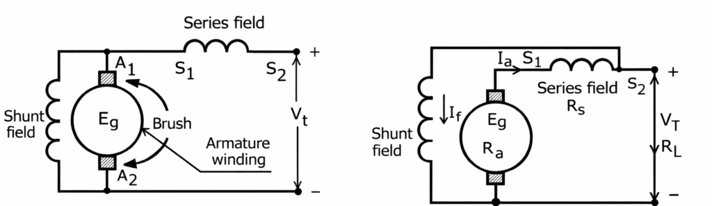
Compound motors are of two types:
• Long shunt compound motor
In this, the shunt field winding is parallel to both armature and series field winding
• Short shunt compound motor
In this the shunt field winding is wired parallel to armature and series field winding is connected in series to the load
They can also be classified as:
• Cumulative compound motor where series field supports shunt field.
• Differential compound motor where series field opposes shunt field.
Applications: presses, rolling mills, heavy duty machines.