What is a Buck Converter?
A buck converter, also referred to as a step-down DC–DC converter or step-down chopper, is a fundamental power electronic circuit used to convert a higher DC input voltage into a controlled lower DC output voltage. It is one of the most widely employed converters in regulated power supplies, battery-operated equipment, motor drives, and embedded systems due to its high efficiency and simple control strategy.
The buck converter achieves voltage regulation by rapidly switching a semiconductor device ON and OFF and controlling the duty ratio of the switching waveform. The average output voltage is therefore a fraction of the input voltage and is always lower than the supply voltage.
Circuit Diagram
Basic Circuit Configuration
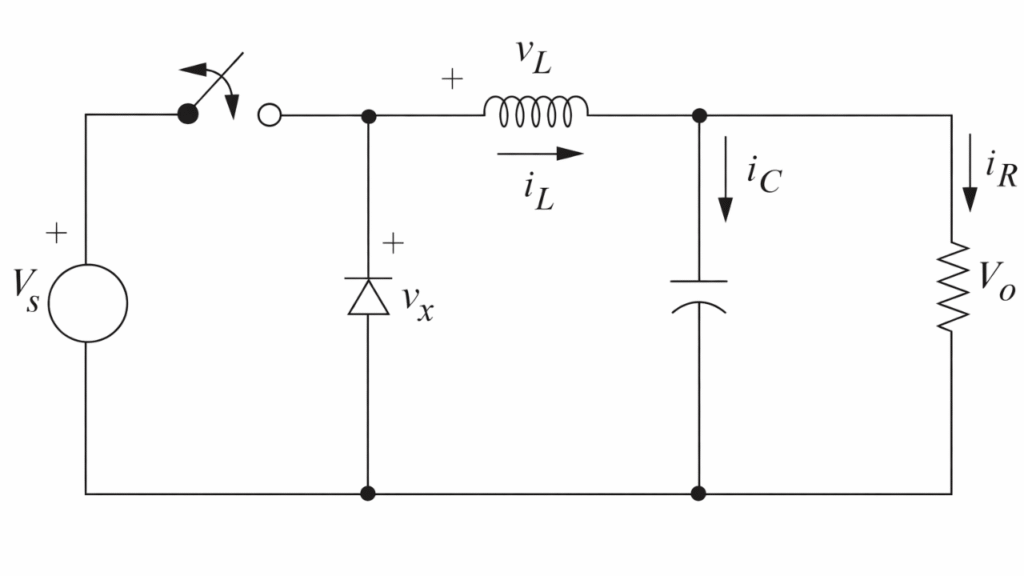
A basic buck converter consists of the following components:
- DC input source (Vs) – supplies constant input voltage
- Controlled switch (S) – thyristor, transistor, MOSFET, or IGBT
- Freewheeling diode (FD) – provides current path during OFF interval
- Inductor (L) – stores energy and smooths current
- Load (R or RL) – receives regulated DC output
Since the load is usually inductive in nature, the current cannot change instantaneously. When the switch is turned OFF, the inductor attempts to maintain current flow, producing a back electromotive force (EMF). To safely provide a path for this current and protect the switching device, a freewheeling diode is connected across the load. Without this diode, the induced voltage may become very large and damage the switching device.
There are two modes of operation of the Buck converter. They are:
- Mode I: Switch1 is ON and Diode FD is OFF
- Mode II: Switch1 is OFF and Diode FD is ON
Mode I: Switch ON Interval (0 ≤ t ≤ Ton)
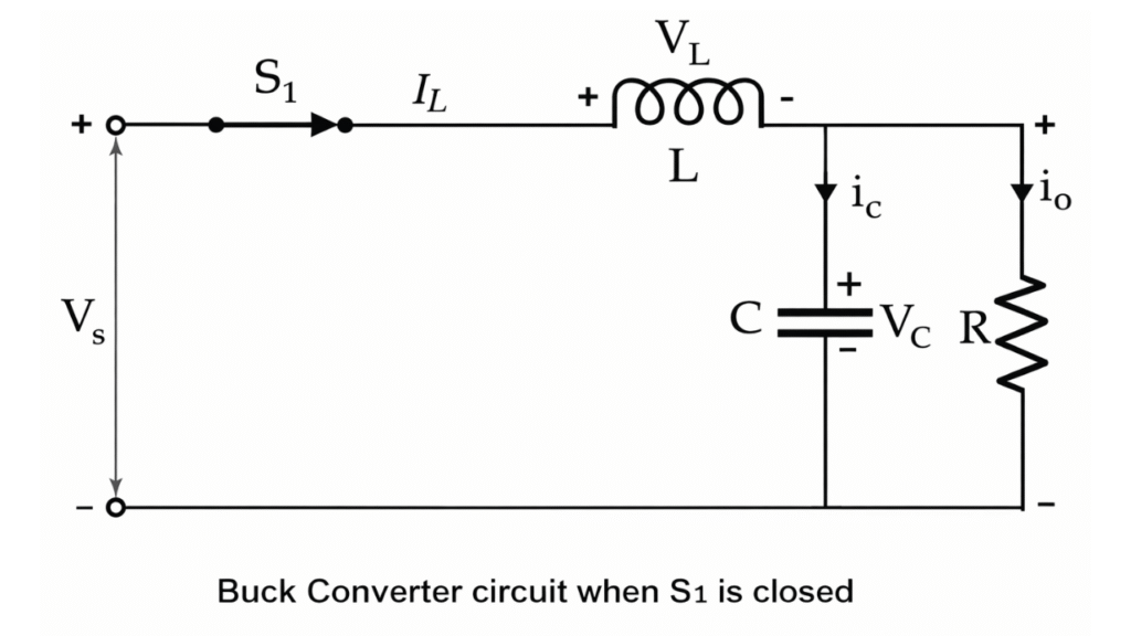
In this mode, the main switch S is turned ON and the diode D is reverse biased, hence it remains in the non-conducting state. The input voltage Vin is applied directly to the inductor–load circuit.
Current flows from the source through the switch S, the inductor L, the capacitor C, and the load. The inductor stores energy in the form of a magnetic field and the capacitor charges. Since a positive voltage is applied across the inductor, the inductor current increases linearly with time.
The voltage across the inductor is: VL = Vin − Vo
The rate of rise of inductor current is: dIL / dt = (Vin − Vo) / L
Mode II: Switch OFF Interval (Ton ≤ t ≤ T)
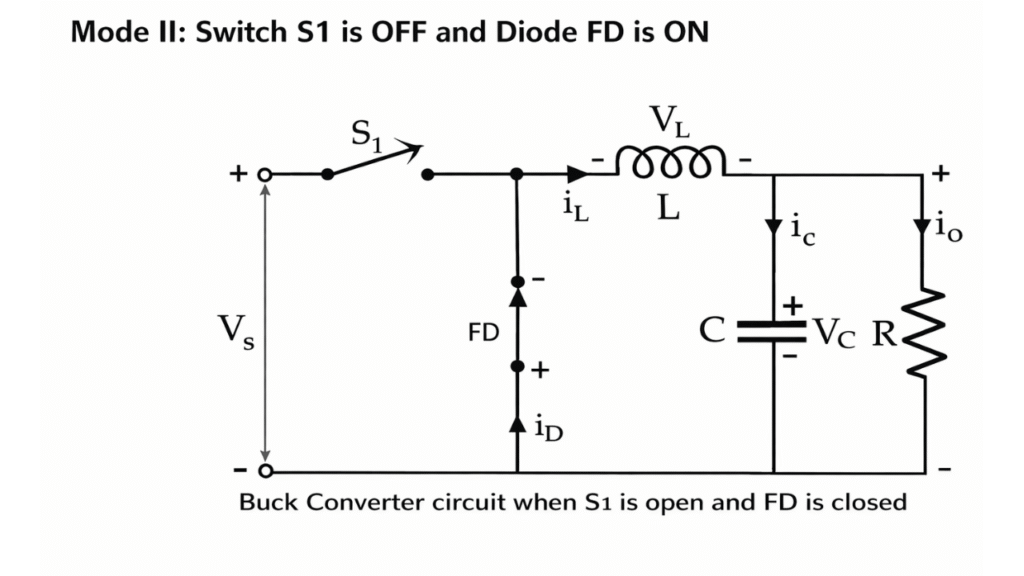
In this mode, the switch S is turned OFF and the diode D becomes forward biased. The energy stored in the inductor during the ON interval is now released to the load through the diode.
The inductor current continues to flow in the same direction through the diode, capacitor, and load. The capacitor supplies current to the load and helps maintain a nearly constant output voltage. Since the voltage across the inductor is now negative, the inductor current decreases linearly.
The voltage across the inductor in this interval is: VL = − Vo
The rate of fall of inductor current is: dIL / dt = − Vo / L
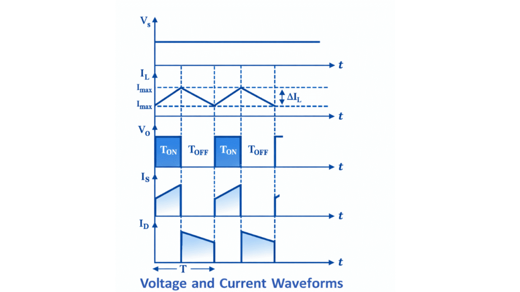
Waveform of Buck Converter
Steady-State Voltage Conversion Ratio
For continuous conduction mode, applying the inductor volt-second balance principle: Vo = D × Vin
Where:
- D = Duty cycle = Ton / T
- Vin = Input voltage
- Vo = Output voltage
This shows that the output voltage is directly proportional to the duty cycle.
Inductor Current Ripple
The peak-to-peak ripple in inductor current is:
ΔIL = (Vin − Vo) × Ton / L
A larger inductance reduces current ripple and improves output current smoothness.
Output Voltage Ripple
The output voltage ripple is mainly due to the charging and discharging of the capacitor and can be expressed as:
ΔVo = ΔIL / (8 f C)
Where:
- f = Switching frequency
- C = Output capacitance
Advantages of Buck Converter
- High efficiency compared to linear regulators
- Compact size and lightweight
- Wide input voltage operating range
- Good output voltage regulation
- Suitable for battery-powered systems
Limitations of Buck Converter
- Generates switching noise and EMI
- Requires careful design of filter components
- Control circuitry increases complexity
- Output voltage always lower than input voltage
Applications of Buck Converter
- Switched-mode power supplies (SMPS)
- Mobile phone and laptop power adapters
- Battery chargers and power banks
- Embedded systems and microcontroller supplies
- Electric vehicles and renewable energy systems
Conclusion
The buck converter is a fundamental and highly efficient DC–DC converter used for stepping down DC voltage levels. By controlling the duty ratio of the switching device, a precisely regulated output voltage can be obtained from a constant DC input. Owing to its simplicity, high efficiency, and excellent performance, the buck converter remains one of the most important building blocks in modern power electronic systems.
Frequently Asked Questions (FAQ) – Buck Converter
What is the function of the inductor in a buck converter?
The inductor stores energy when the switch is ON and releases it when the switch is OFF. It smooths the current waveform and ensures continuous current flow to the load.
What is the relation between duty cycle and output voltage?
In continuous conduction mode, the output voltage is given by: Vo = D × Vin
where D is the duty cycle, Vin is the input voltage, and Vo is the output voltage.
What is discontinuous conduction mode (DCM)?
In discontinuous conduction mode, the inductor current falls to zero for a portion of the switching period. This mode usually occurs at light load conditions and results in higher current ripple and more complex control behavior.
What is the role of the capacitor in a buck converter?
The capacitor reduces output voltage ripple and supplies current to the load during switching transitions, helping to maintain a nearly constant output voltage.
What is discontinuous conduction mode (DCM)?
In discontinuous conduction mode, the inductor current falls to zero for a portion of the switching period. This mode usually occurs at light load conditions and results in higher current ripple and more complex control behavior.