Introduction
A Buck-Boost Converter is a type of DC–DC power electronic converter that can either step down (buck) or step up (boost) the input voltage depending on the duty cycle of the switching device. Unlike buck or boost converters which operate only in one direction of voltage conversion, the buck-boost converter provides a flexible output voltage that can be higher or lower than the input.
This feature makes the buck-boost converter highly useful in battery-powered systems, portable electronics, renewable energy systems, and regulated power supplies where the input voltage varies widely.
Basic Circuit Diagram
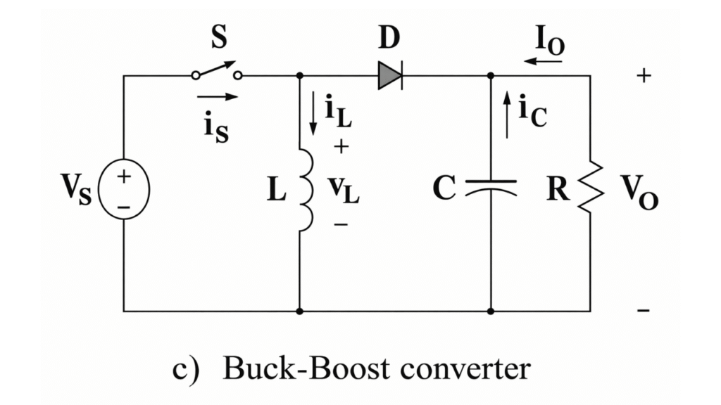
The basic buck-boost converter consists of:
- DC input voltage source (Vin)
- Inductor (L)
- Power switch (MOSFET or transistor)
- Diode (D)
- Output capacitor (C)
- Load resistance (R)
The output voltage polarity is opposite to the input voltage in the conventional buck-boost configuration.
Working Principle
The operation of the buck-boost converter is based on energy storage in the inductor and controlled transfer of this energy to the output through high-frequency switching.
The converter mainly works in two modes during one switching cycle:
- Mode I (Switch ON)
- Mode II (Switch OFF)
Mode I – Switch ON Interval (Energy Storage Mode)
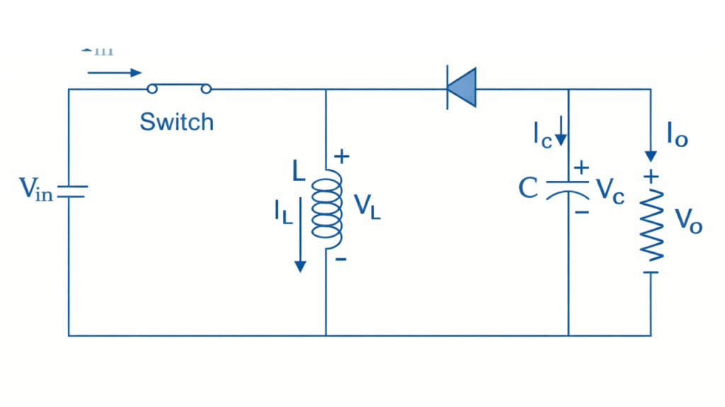
When the switch is turned ON, the diode becomes reverse biased and therefore remains in the non-conducting state. In this interval, the input voltage source is directly applied across the inductor . As a result, the inductor current increases linearly with time and energy is stored in the magnetic field of the inductor. The capacitor , which was previously charged, supplies the load current during this interval because the diode isolates the output stage from the input side.
The voltage across the inductor during this interval is equal to the input voltage:
Hence, the rate of change of inductor current is given by:
For an ON time of Ton, the increase in inductor current is:
During this mode, no power is delivered to the load from the source, and the load is supplied only by the energy stored in the capacitor.
Mode II – Switch OFF Interval (Energy Transfer Mode)
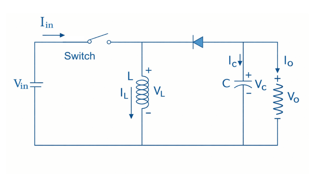
When the switch is turned OFF, the inductor current cannot change instantaneously. To maintain current continuity, the polarity of the inductor voltage reverses, which forward biases the diode . Consequently, the stored energy in the inductor is transferred to the capacitor and the load. In this interval, the inductor, capacitor, and load form a closed loop, allowing energy to flow from the inductor to the output side.
The voltage across the inductor during this interval is:
Therefore, the rate of change of inductor current becomes:
For an OFF time of Toff, the decrease in inductor current is:
In this mode, both the inductor and the capacitor supply energy to the load, while the capacitor also gets charged to the required output voltage.
Steady-State Condition and Voltage Conversion Ratio
In steady-state operation, the net change in inductor current over one complete switching period must be zero. Therefore,
Substituting the expressions obtained earlier:
Dividing both sides by the switching period and defining the duty cycle as , we obtain the voltage conversion ratio:
The negative sign indicates that the output voltage polarity is reversed with respect to the input voltage. By adjusting the duty cycle, the magnitude of the output voltage can be made either greater than or less than the input voltage.
Voltage Conversion Ratio
For continuous conduction mode (CCM), the relationship between output voltage and input voltage is: Vout / Vin = – D / (1 – D)
Where:
D= Duty cycle of the switch (Ton / T)
The negative sign indicates that the output voltage polarity is reversed with respect to the input.
Output Voltage Characteristics
- If
D < 0.5→ Output voltage magnitude is less than input (Buck mode) - If
D > 0.5→ Output voltage magnitude is greater than input (Boost mode) - If
D = 0.5→ |Vout| = Vin
Thus, the converter can work as both buck and boost by controlling the duty cycle.
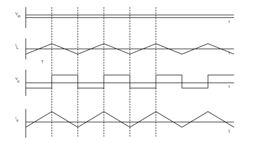
Waveform
Applications of Buck-Boost Converter
- Used in battery-powered devices to maintain a constant output voltage as the battery voltage varies.
- Applied in solar energy systems for regulating fluctuating panel voltages and charging batteries efficiently.
- Employed in electric and hybrid vehicles for voltage matching between batteries and DC buses.
- Used in LED driver circuits for accurate voltage and current control.
- Applied in embedded systems and microcontroller power supplies to generate stable logic voltages from unregulated sources.
- Used in telecommunication and industrial electronics to supply regulated DC voltages to sensitive circuits.
Conclusion
Thus, during the ON interval the buck-boost converter stores energy in the inductor, and during the OFF interval this stored energy is transferred to the output. The combined action of these two modes enables the converter to provide a regulated output voltage whose magnitude can be either higher or lower than the input, with inverted polarity. This operating principle makes the buck-boost converter highly suitable for applications requiring wide input voltage regulation.