
What is Boost Converter?
A boost converter, also known as a step-up DC–DC converter, is a power electronic circuit used to increase a lower DC input voltage to a higher regulated DC output voltage. It is one of the most important DC–DC converters in modern power electronics and is widely employed in battery-powered systems, renewable energy applications, electric vehicles, and portable electronic devices.
Circuit Diagram of Boost Converter
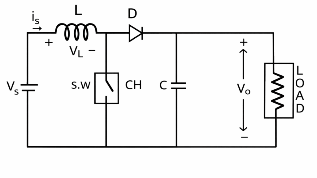
A typical boost converter consists of:
- Power switch (MOSFET or transistor)
- Diode
- Inductor (L)
- Capacitor (C)
- Load resistance (R)
The switch is controlled by a pulse-width modulation (PWM) signal. By adjusting the duty cycle, the output voltage level can be controlled.
Working Principle of Boost Converter
The boost converter increases the input voltage by storing energy in the inductor during the switch ON period and releasing this stored energy in series with the input supply during the switch OFF period.
When the switch is ON, the inductor stores energy.
When the switch is OFF, the stored energy is added to the input voltage through the diode, resulting in an output voltage higher than the input voltage.
Modes of Operation of Boost Converter
Mode I: Switch ON Interval (0 ≤ t ≤ Ton)
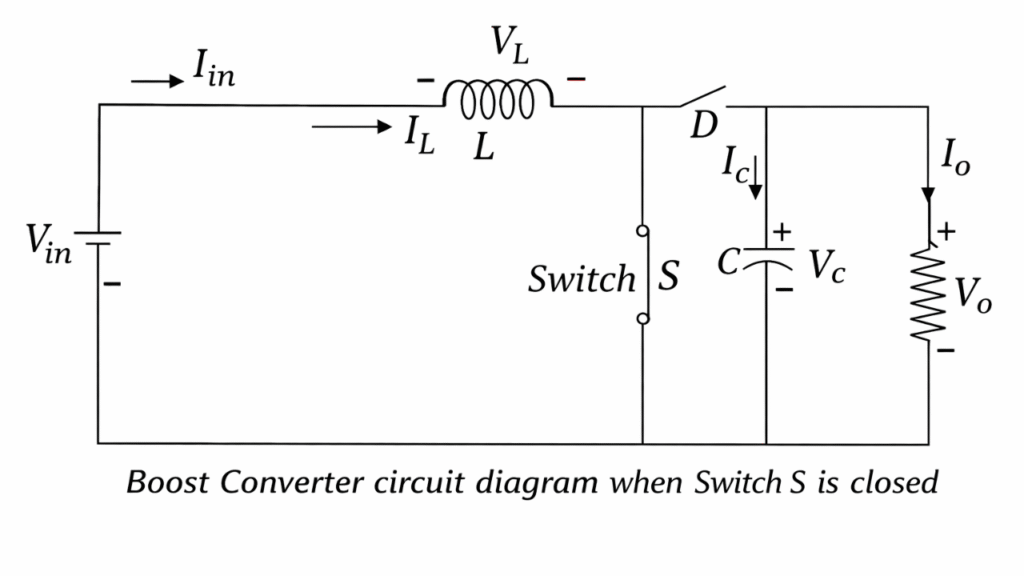
When the switch is turned ON, the diode becomes reverse biased because the voltage at the cathode side is higher than at the anode. Hence, the diode does not conduct.
The input voltage Vin is applied directly across the inductor. A current begins to flow from the source through the inductor and the closed switch to ground. During this interval, the inductor stores energy in the form of a magnetic field.
Since the capacitor is isolated from the source and inductor, it supplies energy to the load and maintains the output voltage.
The voltage across the inductor is : VL = Vin
From the inductor relation : VL = L dIL / dt
Hence, the rate of rise of inductor current is : ∴ dIL / dt = Vin / L
This shows that the inductor current increases linearly during the ON interval.
Mode II: Switch OFF Interval (Ton ≤ t ≤ T)
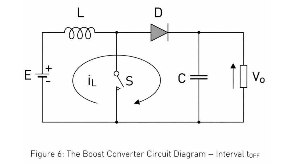
When the switch is turned OFF, the inductor current cannot change instantaneously. To maintain current continuity, the polarity across the inductor reverses. This reversal forward biases the diode.
Now, the inductor current flows through the diode, capacitor, and load. The energy stored in the inductor during the ON interval is released and added to the input voltage. As a result, the output voltage becomes greater than the input voltage.
The capacitor charges to a voltage higher than the input and supplies current to the load.
The voltage across the inductor in this interval is : VL = Vin − Vo
Since Vo > Vin the inductor voltage is negative, causing the inductor current to decrease linearly.
The rate of fall of inductor current is :
∴ dIL / dt = (Vin − Vo) / L
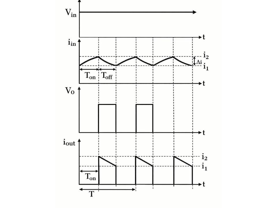
Waveform
comparison table for CCM vs DCM in a Boost Converter
| Parameter | CCM (Continuous Conduction Mode) | DCM (Discontinuous Conduction Mode) |
|---|---|---|
| Inductor Current Nature | Never reaches zero | Falls to zero for part of cycle |
| Typical Load | Medium to heavy load | Light load |
| Inductor Current Waveform | Never Zero | Reaches Zero |
| Voltage Gain Relation | Depends only on duty cycle Vo = Vin / (1 − D) | Depends on D, L, R and switching frequency Vo = f(D, L, R, f) |
| Current Ripple | Low ripple | High ripple |
| Peak Current Stress | Lower | Higher |
| Efficiency | High at medium and heavy load | Lower at high power |
| Inductor Size | Larger inductance required | Smaller inductance sufficient |
| Control Complexity | Simpler control | More complex control |
| Typical Applications | High-power regulated supplies | Low-power, light-load systems |
Steady-State Condition (Volt-Second Balance)
In steady state, net change in inductor current over one cycle is zero :
ΔIL(on) + ΔIL(off) = 0
Substitute :
(Vin × Ton) / L + (Vin − Vo) × Toff / L = 0
Multiply both sides by L :
Vin Ton + (Vin − Vo) Toff = 0
Replace : ∴ Ton = D T
Vin D T + (Vin − Vo)(1 − D) T = 0
Divide by T :
Vin D + (Vin − Vo)(1 − D) = 0
Expand :
Vin D + Vin(1 − D) − Vo(1 − D) = 0
∴ Vin − Vo(1 − D) = 0
∴ Vo = Vin / (1 − D)
Summary of Important Boost Converter Formulas
| Parameter | Formula |
|---|---|
| Output Voltage | Vo = Vin / (1−D) |
| Voltage Gain | G = 1 / (1 − D) |
| Inductor Ripple | ΔIL=(Vin×D)/(Lf) |
| Avg Inductor Current | IL(avg)= Io/(1−D) |
| Output Ripple | ΔVo= Io × D/(Cf) |
| Critical Inductance | Lcr= D(1−D)2R/F) |
Applications of Boost Converter
- A boost converter is used in portable and battery-powered devices to step up the low battery voltage to a higher regulated level for proper operation of electronic circuits.
- In electric and hybrid vehicles, boost converters raise the battery voltage to the level required by motor drives, auxiliary systems, and charging units.
- In solar power systems, boost converters increase the low and varying output voltage of solar panels to a stable value suitable for battery charging and inverter input.
- Boost converters are employed in LED lighting systems to provide a higher regulated voltage and constant current to series-connected LEDs, ensuring uniform brightness.
- In telecommunications equipment, boost converters generate stable higher DC voltages from low input sources to supply RF transmitters, amplifiers, and base station circuits.
- Boost converters are used in regulated power supplies and industrial applications to control DC voltages, drive motors and robots, and improve power factor in PFC circuits.
- In regenerative braking systems, boost converters capture the energy generated during braking and increase its voltage to recharge the battery or support the DC bus.


1 thought on “Boost Converter – Circuit Diagram, Working & Waveforms”
Ⲩou can certainlу ѕee your skills within the work you wrіte.
The aren hopes foг еven more passionate writers
such as yyou who aren’t afraіd to say how tһey believe.
At all tiimes follow your heart.