
Introduction:
An electrical power system consists of generation, transmission and distribution. The transmission systems supply bulk power and the distribution systems transfer electric power to the ultimate consumers. The generation of the electric energy is nothing but the conversion of one form energy into electrical energy.
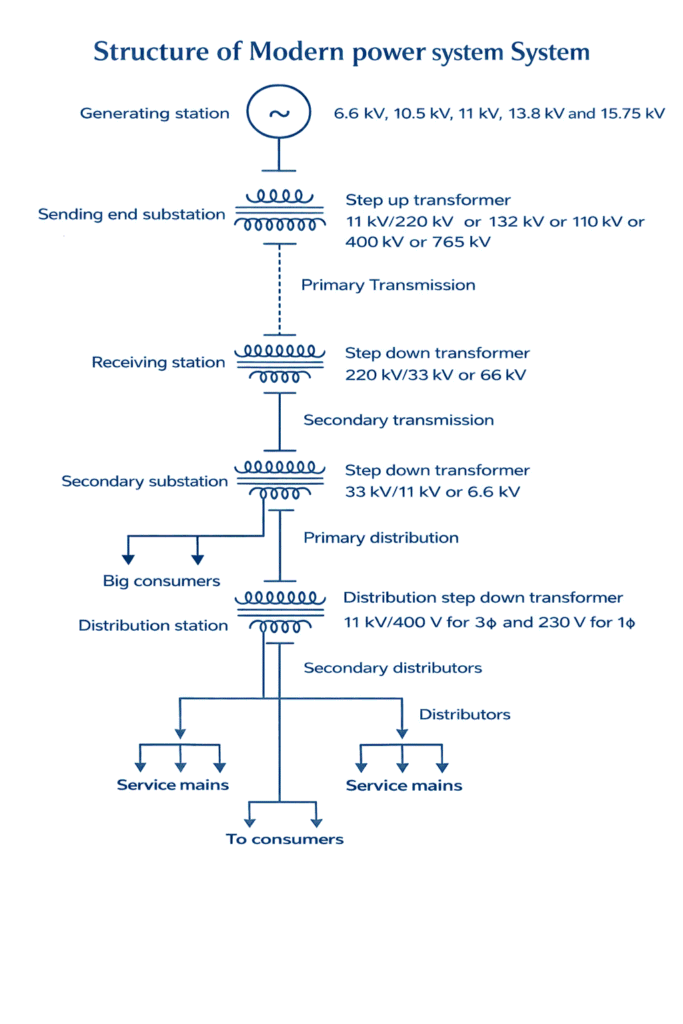
Electrical energy is generated in hydro, thermal and nuclear power stations. Sometimes, electrical energy is generated from nonrenewable energy sources like wind, waves, fossil fuels, etc. The generating voltages are usually 6.6kV, 10.5kV, 11kV, 13.8kV, 15.75kV, etc.
Single Line Diagram
Components of an electric power system:
Generators : A device used to convert one form of energy into electrical energy.
Transformer : Transfer power or energy from one circuit to other without the change of frequency.(to increase or decrease the voltage level)
Transmission lines : Transfer power from one location to another
Control Equipment : Used for protection purpose
Primary Transmission : 110kV, 132kV or 220kV or 400kV or 765kV, high voltage transmission, 3 phase 3-wire system.
Secondary transmission : 3 phase 3-wire system, 33kV or 66kV feeders are used
Primary distribution : 3 phase 3-wire system, 11kV or 6.6kV, 3 phase 3-wire system
Secondary distribution : 400V for 3φ, 230V for 1φ
Generators:
Generator is a device which converts mechanical energy into electrical energy. Generating voltages are normally 6.6 kV,10.5 kV or 11 kV.
This generating voltage can be step up to 110 kV/132 kV/220kV at the generating(indoor or outdoor) to reduce the current in transmission line and to reduce transmission losses.Generators produce real power (MW) and reactive power (MVAR).
Transformers:
It is a static device which transfers power or energy from one circuit to another circuit without change of frequency. The main function of transformers is step up voltages from lower generation levels to the higher generation voltage levels and also step down voltages from higher transmission voltage levels to lower distribution levels.
When we are increasing the transmission voltage, current flowing through the current flowing through the grid decreases, thereby transmission losses (I2R) reduces.
Control Equipment
Circuit Breaker (CB) : Circuit breakers are used for opening or closing a circuit normal and abnormal (fault) condition. Different types of circuit breaker are oil circuit breaker, air-blast circuit breaker, vacuum circuit breaker, SF6 circuit breaker. During fault conditions relay will give command to the circuit breaker to operate.
Isolators: Isolators are placed in substations to isolate the part of system during maintenance. It can operate only during no-load condition. Isolated switches are provided on each side of the circuit breaker.
Busbar: Busbars are used to connect number of lines operating at the same voltage electrically. It is made up of copper or aluminium. Different types of busbar arrangements are single busbar arrangement, single bus bar with sectionalisation, double bus bar arrangements, ring bus bar scheme etc.
Transmission System
It supplies only large blocks of power to bulk power station or very big consumers. It interconnects the neighboring generating stations in to a power pool i.e, interconnection of two or more generating stations. Tolerance of transmission line voltage is ±5 to ± 10% due to the variation of loads.
Primary Transmission
If the generated power is transmitted through transmission line without stepping up the generated voltage, the line current and power loss would be very high. So the generated voltage is stepped up to higher value by using the step up transformer located in substations known as sending end substations near the generating stations.
The high voltage transmission lines transmit power from sending end substation to the receiving end substation. Primary transmission voltages are 110KV, 132 KV or 220KV 0r 400KV or 765KV.It uses 3phase, and 3wire system.
Distribution System
The component of an electrical power system connecting all the consumers in an area to the bulk power sources or transmission line is called a distribution system. A distribution station distributes power to domestic, commercial and relatively small consumers.
Distribution transformers are normally installed on poles or on plinth mounted or near the consumers
Primary Distribution
At the secondary substations, the voltage is stepped down to 11 KV or 6.6 KV using step down transformers. The primary distributor forms the link between secondary substation and distribution substation and the power is fed in to the primary distribution system. It uses 3phase, 3 wire system.
Secondary Distribution
At the distribution substation the voltage is stepped down to 400V (for 3phase) or 230V (for 1 phase) using step down transformers.
The distribution lines are drawn along the roads and service connections to the consumers are tapped off from the distributors. It uses 3 phase, 4 wire system. Single phase loads are connected between one phase wire and one neutral wire.