
Electrical Power Generation
The generation of electric energy is most commonly achieved through electric machines specifically generators (for DC) or alternators (for AC), which convert mechanical energy into electrical energy based on the principle of electromagnetic induction, discovered by Michael Faraday.
In India, especially in regions like Maharashtra (including areas around Airoli and Navi Mumbai), electricity powers homes, industries, IT hubs, railways, and everyday life from charging your phone to running Mumbai’s local trains or powering factories in MIDC zones. But where does this power actually come from? Let’s break it down in a simple, India-focused way, using the basic sources you mentioned: Water, Fuels, and Nuclear energy, along with the rapidly growing others that are shaping our grid in 2025–2026.
Generation of electric energy is most commonly done by electric machines, i.e. generator or alternator, which converts mechanical energy into electrical energy.
Basic source of energy used for generation of electricity:
- Water
- Fuels
- Nuclear energy
Classification of Power Stations
Depending upon the type of energy converter used, power stations are classified as follows.
Thermal Power Stations
In these power stations, chemical energy of fuel (coal, eil, gas etc.) is converted into electrical energy. The fuel used may be coal or diesel. The heat of combustion of fuels is utilized in boilers to raise the temperature and pressure of steam. The steam produced is utilized in driving the steam turhines coupled to generators and thus in generating electrical energy.
Classification of Thermal Power Stations
According to the prime mover employed for driving the alternator, thermal power stations may be broadly divided into following types:
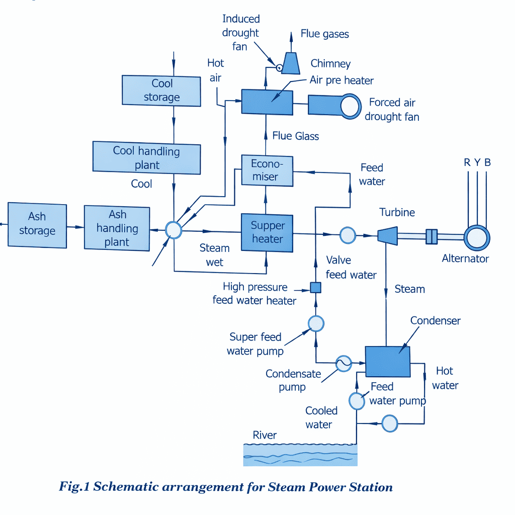
Steam Power Station
In these power stations coal is used as a fuel and steam turbine is used as a prime mover.
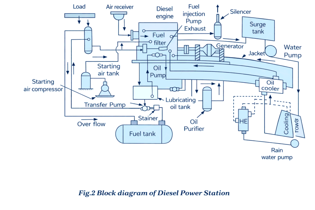
Diesel Power Station
Hydro-Electric Power Stations
These power stations utilize potential energy of water at a high level for the generation of electrical energy. Ample amount of water head is created by constructing a dam across a river. The pressure head of water or kinetic energy of water is utilized to drive the water turbines coupled to alternators and therefore generation of electrical power. A hydroelectric power station consists of a reservoir for storage of water, a diversion dam, an intake structure for controlling and regulating flow of water (called surge tank), a conduct system to carry the water from the intake to the water wheel (called penstock), the turbines coupled to generators, the draft tube for conveying water from water wheel to tailrace, the tailrace to a power house.
When water drops through a height, its energy is able to rotate turbines which are coupled to alternators.
Electric power, P = Q H η kilowatt
where,
Q = discharge, m³/sec
H = water head, m
η = overall efficiency of turbine alternator set.
Classification of Hydro-Electric Power Stations
Hydro-electric plants may be classified according to the available head as :
Low Head Plants
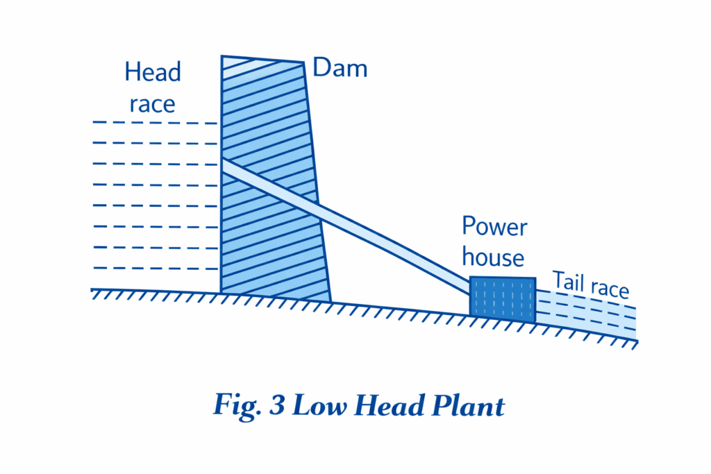
For such plants a small dam is constructed across the river to provide necessary head. The excess water is allowed to flow over the dam itself. No surge tank is required for such plants.
Medium Head Plants
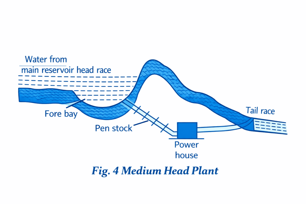
The forebay provided at the beginning of penstock serves as water reservoir for such plants. In such plants water is generally carried in open channels from main reservoir to the forebay and then to the power house through the penstock. The forebay itself works as surge tank in this case. Common type of prime movers used in these plants : Francis, Propeller and Kaplan.
Classification of turbines according to range of head and specific speed :
| Type of turbine | Head | Specific speed |
|---|---|---|
| Pelton | Above 200 m | 10 – 50 |
| Francis | 30 m – 200 m | 60 – 300 |
| Propeller | Less than 30 m | 300 – 1000 |
High Head Plants
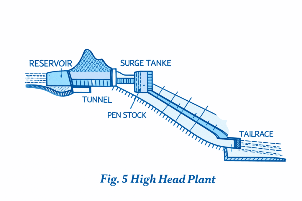
In such plants first of all water is carried from the main reservoir by a tunnel upto the surge tank and then from the surge tank to the power house in pen stocks.
Pumped Storage Plants
It is a special type of plant meant to supply peak loads. During peak load period, water is drawn from the head water pond through the penstock and generates power for supplying the peak load. During the off‑peak period, the same water is pumped back from the tail water pond to the head water pond so that this water may be used to generate energy during the next peak load period. Thus the same water is used again and again and extra water is needed only to take care of evaporation and seepage. For this purpose a reversible turbine pump is used. During peak loads the turbine drives the alternator and the plant generates electrical energy using an extra motor for pumping water and drives the turbine which now works as a pump for pumping the water into the head water pond.
Water turbines
These are used to convert the energy of falling water into mechanical energy.
Principal types of water turbines
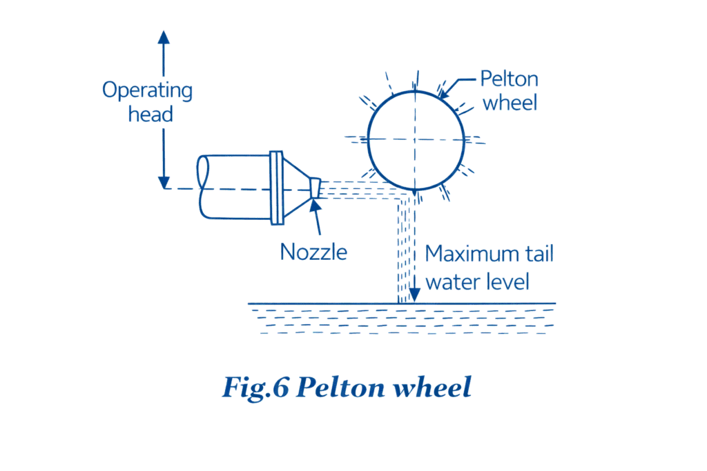
- Impulse turbines: Such turbines are used for high heads. In an impulse turbine, the entire pressure of water is converted into kinetic energy in a nozzle and the velocity of the jet drives the wheel. The example of this type of turbine is the Pelton wheel. It consists of a wheel fitted with elliptical buckets along its periphery. The force of water jet striking the buckets on the wheel drives the turbine. The quantity of water jet falling on the turbine is controlled by means of a needle or spear (not shown in the figure) placed in the tip of the nozzle. The movement of the needle is controlled by the governor. If the load on the turbine decreases, the governor pushes the needle into the nozzle, thereby reducing the quantity of water striking the buckets. Reverse action takes place if the load on the turbine increases.
- Reaction turbines: Reaction turbines are used for low and medium heads. In a reaction turbine, water enters the runner partly with pressure energy and partly with velocity head.
Important types of reaction turbines
- Francis turbines: It is used for low to medium heads. It consists of an outer ring of stationary guide blades fixed to the turbine casing and an inner ring of rotating blades forming the runner. The guide blades control the flow radially inwards and changes to a downward direction while passing through the runner. As the water passes over the “rotating blades” of the runner, both pressure and velocity of water are reduced. This causes a reaction force which drives the turbine.
- Kaplan turbines: It is used for low heads and large quantities of water. It is similar to Francis turbine except that the runner of Kaplan turbine receives water axially. Water flows radially inwards through regulating gates all around the sides, changing direction in the runner to axial flow. This causes a reaction force which drives the turbine.
Nuclear Power Stations
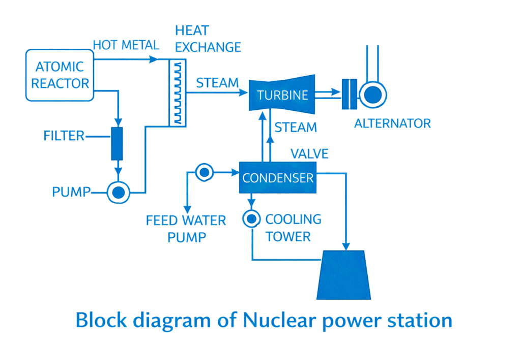
These convert nuclear energy into electrical energy. The tremendous amount of heat energy produced in breaking of atoms of Uranium or other similar metals of large atomic weight into metals of lower atomic weight by fission process in an atomic reactor is utilized in converting water into steam. The steam so generated is utilized in driving gas or steam turbine coupled to generator. The plant consists of nuclear reactor (for heat generation), heat exchanger (for converting water to steam by using heat generated in nuclear reactor), steam turbine, alternator, condenser etc.
Nuclear reactor:
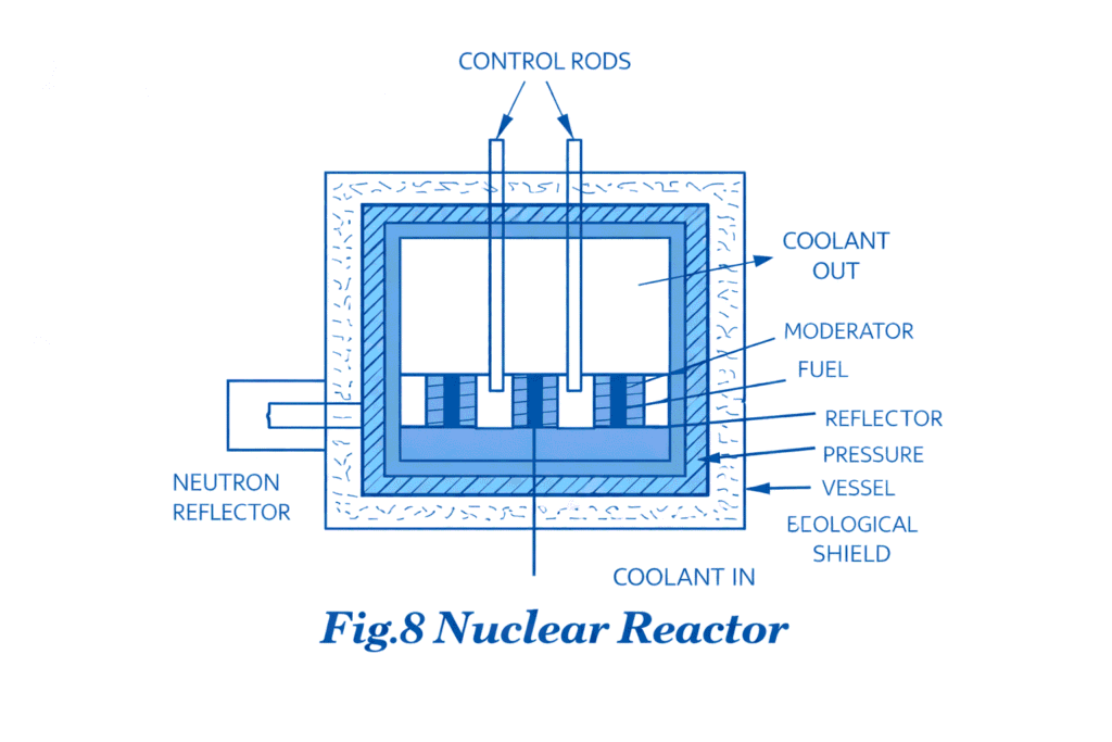
The purpose of moderator in the reactor core is to moderate or reduce the neutron speeds to a value that increases probability of fission occurring.
Commonly used moderators :
(i) Graphite
(ii) Heavy water
(iii) Beryllium
Control rod : It is used in the reactor to initiate the chain reaction and to maintain its reaction at a steady value during operation of the reactor. It also shuts down the reactor automatically under emergency conditions. The materials used for control rods must have very high absorption capacity for neutrons.
Commonly used materials for control rod : Cadmium, Boron or Helium.
Types of fuels used in Nuclear reactors :
(i) Uranium 92 U²³⁵
(ii) Secondary Uranium 92 U²³³
(iii) Plutonium 94 Pu²³⁹
Reactors used in nuclear power plant
| No. | Types of Reactor | Fule Used | Coolant Used | Moderator Used |
|---|---|---|---|---|
| 1. | Advanced Gas Cooled Reactor (AGR) | Uranium dioxide | CO₂ | Graphite |
| 2. | Magnox Reactor | Natural uranium | CO₂ | Graphite |
| 3. | Pressurised Water Reactor (PWR) | Enriched uranium oxide | Pressurised water | Pressurised water |
| 4. | Boiling Water Reactor (BWR) | Enriched uranium oxide | Water | Water |
| 5. | Liquid Metal Fuelled Reactor | Uranium in sodium | Sodium | Graphite |
Fast reactor
It reactor produces heat and at the same time converts fertile material (U²³⁸ and Th²³²) into Fissile material (Pu²³⁹ and U²³³). It is also called fast breeder.