
What is Cuk Converter?
The Cuk converter is a DC–DC power electronic converter capable of producing an output voltage that is either higher or lower than the input voltage, with reversed polarity. It is an improved version of the buck–boost converter that provides continuous input current and continuous output current, which results in reduced ripple and better electromagnetic compatibility. Because of these advantages, the Ćuk converter is widely used in high‑performance power supplies, battery systems, and renewable energy interfaces.
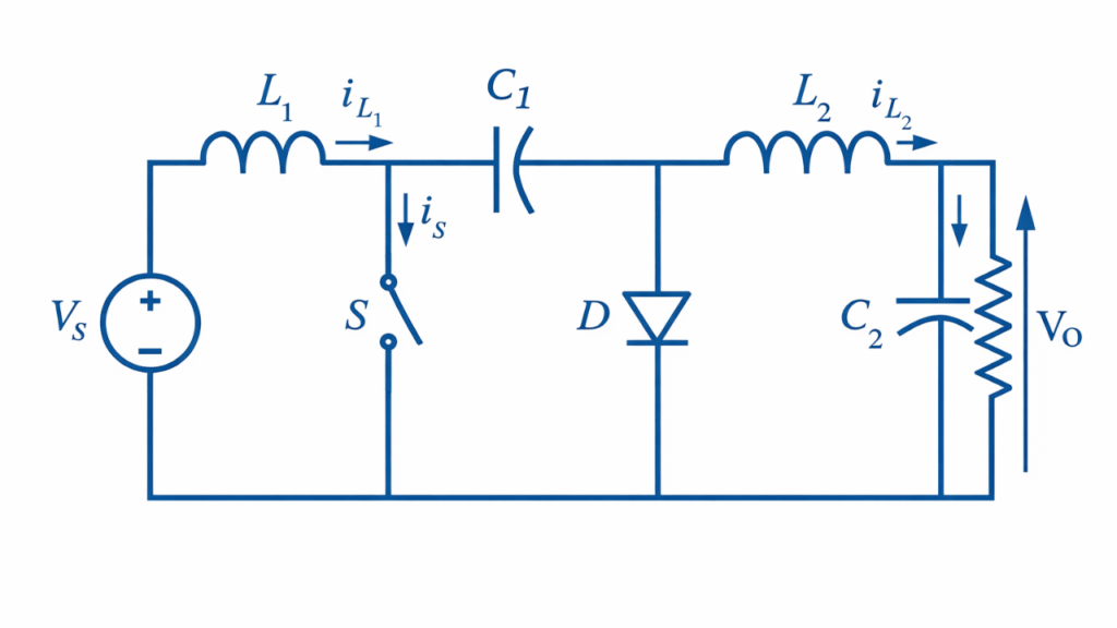
Basic Circuit Diagram
The Cuk converter consists of two inductors, one energy‑transfer capacitor, a switch, a diode, and a load. The capacitor plays a central role by transferring energy from the input side to the output side.
Modes of Operation of Cuk Converter
The operation of the Cuk converter can be divided into two main modes during one switching cycle, assuming continuous conduction mode.
- Mode I – Switch ON Interval
- Mode II – Switch OFF Interval
Mode I – Switch ON Interval
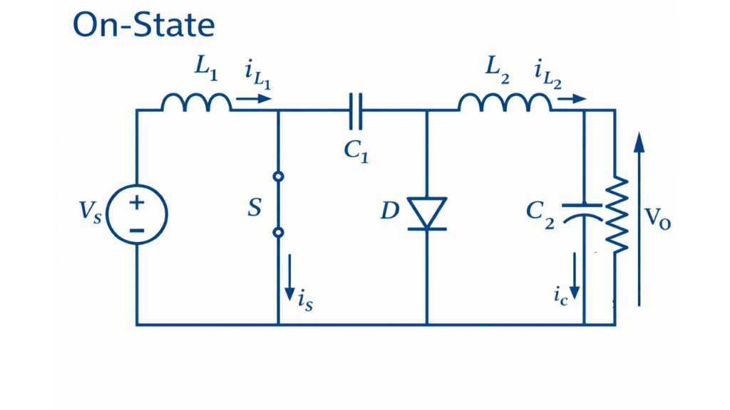
When the switch is turned ON, the diode becomes reverse biased and remains non-conducting. In this interval, the input source supplies energy directly to inductor , causing its current to increase linearly and store energy in its magnetic field. At the same time, the energy-transfer capacitor , which was charged during the previous interval, discharges through inductor and the load, thereby supplying energy to the output. Thus, during this mode, inductor stores energy from the input while inductor delivers energy to the load using the energy released from the capacitor.
The voltage across the inductors during this interval is given by:
Hence, the rate of change of currents in the inductors is:
During this interval, the capacitor voltage decreases slightly as it transfers energy to the output side, while the output voltage is maintained by the combined action of and the output capacitor.
Mode II – Switch OFF Interval
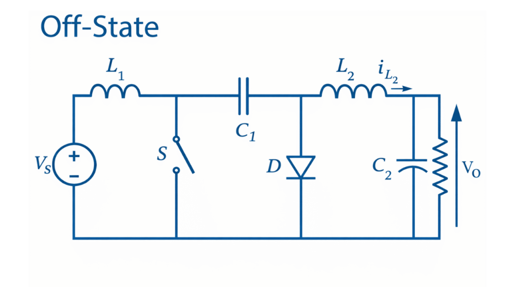
When the switch is turned OFF, the diode becomes forward biased and starts conducting. In this mode, the energy stored in inductor is transferred to the energy-transfer capacitor through the diode, charging the capacitor with reversed polarity. Simultaneously, inductor continues to supply energy to the load and also receives additional energy from the capacitor. Thus, during this interval, both inductors and the capacitor participate in sustaining the output voltage.
The inductor voltages during this interval are:
Therefore, the current variations are:
During this interval, the capacitor stores energy from inductor while simultaneously delivering part of this energy to the output stage.
Steady-State Condition and Voltage Conversion Ratio
In steady-state operation, the average voltage across each inductor over one complete switching period must be zero. Applying the volt-second balance principle to inductor :
which gives:
Applying volt-second balance to inductor L2:
Substituting , the voltage conversion ratio becomes:
The negative sign indicates that the output voltage polarity is reversed with respect to the input voltage, and the magnitude can be either higher or lower depending on the duty cycle.
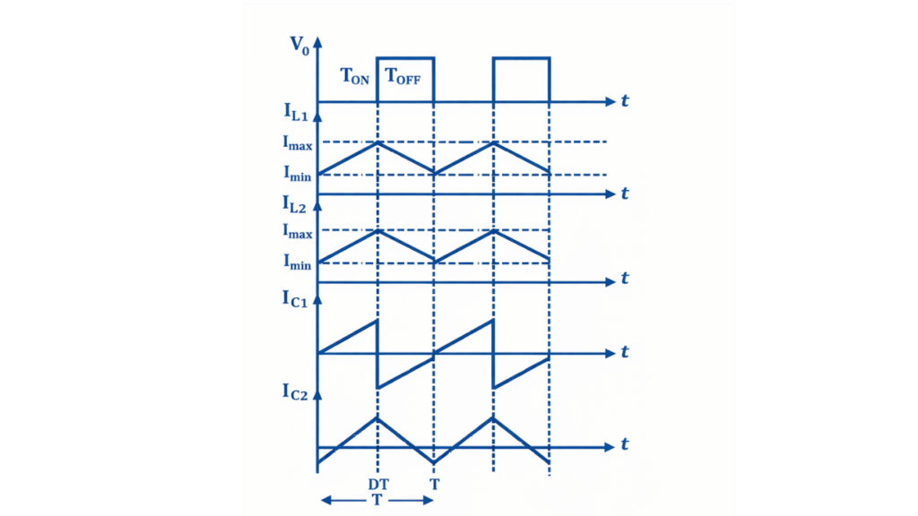
Waveform of Cuk Converter
Applications of Cuk Converter
- Used in battery-powered devices to maintain constant output voltage as battery voltage varies.
- Applied in solar energy systems for regulating fluctuating photovoltaic output voltages.
- Employed in regulated DC power supplies requiring low ripple and continuous current.
- Used in LED driver circuits for precise voltage and current control.
- Used in embedded and microcontroller power supplies to generate stable logic voltages.
- Applied in telecommunication equipment to supply clean and reliable DC power.
Conclusion
Thus, during the ON interval the Cuk converter stores energy in inductor and transfers previously stored capacitor energy to the output, while during the OFF interval the stored energy in is transferred to the capacitor and then to the output through . This complementary energy exchange ensures continuous input and output currents, reduced ripple, and high-quality voltage conversion, making the Ćuk converter highly suitable for precision power electronic applications.