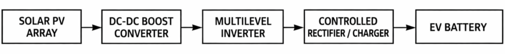
This project builds a solar powered EV charging system that uses a boost converter and a multilevel inverter to efficiently convert solar energy into usable power for charging an electric vehicle battery. The goal is to create a renewable EV charging prototype suitable for an engineering project.
Your available hardware already fits perfectly:
• Solar panels (about 100 W total)
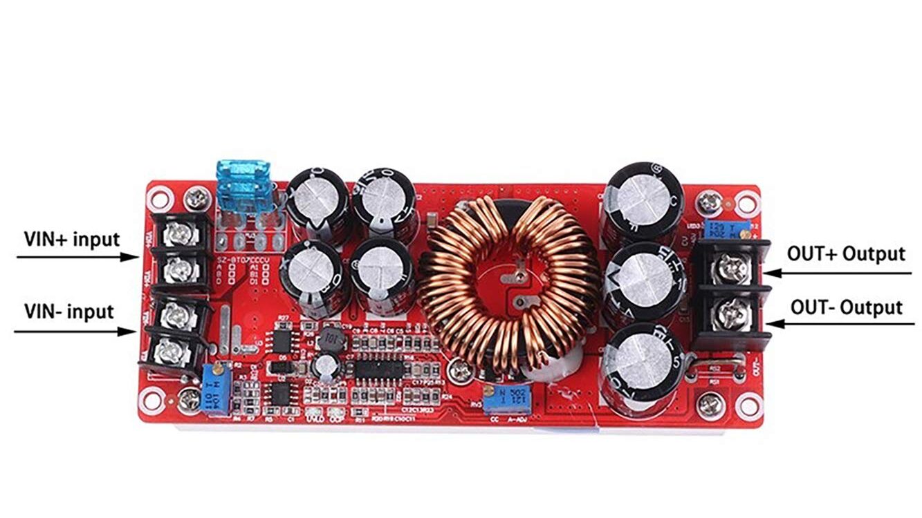
• 1200 W boost converter module
• Multilevel inverter stage
A multilevel inverter produces a stepped voltage waveform that closely resembles a sinusoidal waveform. This improves power quality, reduces switching losses, and increases charging efficiency. When combined with power electronic converters, it becomes possible to design a charger suitable for EV battery systems.
Need for Solar Based EV Charging
The increasing number of electric vehicles creates a higher demand for electricity. If all EVs depend only on conventional power plants, it may increase stress on the electrical grid.
Solar based EV charging systems provide several benefits.
• Reduction in greenhouse gas emissions
• Utilization of renewable energy
• Reduced load on the utility grid
• Energy independence for charging stations
• Lower operating cost over time
Solar powered EV chargers can operate either as grid connected systems or as standalone off grid systems.
Block Diagram
| Block | Function in System | Input Rating | Output Rating |
|---|---|---|---|
| Solar PV Array | Converts sunlight into DC electrical power. Panels are connected in series to increase voltage. | V ≈ 32 V, I ≈ 3.3 A (series connection) | P ≈ 105 W |
| DC DC Boost Converter | Steps up the low PV voltage to a higher DC voltage required for the inverter stage. | 32 V DC, 3.3 A | 100 V DC (approx), 1 A |
| Multilevel Inverter | Converts boosted DC voltage into stepped AC waveform with lower harmonics. | 100 V DC | 70 to 90 V AC |
| Controlled Rectifier / Charger | Converts AC back into controlled DC suitable for battery charging. | 70 to 90 V AC | 48 to 72 V DC |
| EV Battery | Stores electrical energy in the electric vehicle battery pack. | Charging voltage 48 to 72 V | Battery energy storage |
Circuit Diagram of DC DC Boost Converter
5 Level Cascaded H Bridge Multilevel Inverter
Basic Configuration
| Component | Quantity | Function |
|---|---|---|
| DC Sources | 2 | Provide DC input voltage |
| H Bridge Circuits | 2 | Generate positive and negative voltage levels |
| Power MOSFET / IGBT | 8 | Switching devices |
| Gate Driver Circuit | 2 | Drives MOSFET gates |
| Load | 1 | Motor, grid, or charger input |
Output Voltage Levels
For a 5 level inverter, the output voltage becomes
| Switching State | Output Voltage |
|---|---|
| Level 1 | +2Vdc |
| Level 2 | +Vdc |
| Level 3 | 0 |
| Level 4 | −Vdc |
| Level 5 | −2Vdc |
This stepped waveform reduces harmonic distortion compared to a normal inverter.
Main Components
| Component | Example Rating |
|---|---|
| MOSFET | IRF3205 or IRFP460 |
| Gate Driver | IR2110 |
| DC Source | Boost converter output |
| Filter | LC filter optional |
| Controller | Arduino / DSP / PWM controller |
How It Connects to Your System
Your system structure becomes
Solar PV Array → Boost Converter → Multilevel Inverter → Controlled Rectifier → EV Battery
Example voltage flow
| Stage | Voltage |
|---|---|
| Solar Panels | 30 to 35 V |
| Boost Converter Output | 90 to 120 V DC |
| Multilevel Inverter Output | 80 to 100 V AC |
| Rectifier Output | 60 to 72 V DC |
| EV Battery Charging | 48 to 72 V |
Advantages of Multilevel Inverter
Lower harmonic distortion
Higher efficiency
Reduced switching losses
Better voltage waveform
Suitable for renewable energy systems
Recommended Type for Your Project
| Type | Difficulty | Suitability |
|---|---|---|
| Diode Clamped | High | Medium |
| Flying Capacitor | High | Medium |
| Cascaded H Bridge | Easy | Best |
Cascaded H Bridge is best because it is easier to design and commonly used in solar applications