Air-blast circuit breakers were widely used before the 1980s for voltage levels ranging from 11 kV to 1100 kV. A compressor plant is required to maintain high air pressure in the air receiver. During the period 1950–1970, air-blast circuit breakers were preferred for 220 kV and above. However, today SF₆ circuit breakers are preferred for this voltage range. For 11 kV and 33 kV applications, vacuum circuit breakers (VCBs) are preferred. As a result, air-blast circuit breakers have become obsolete.
These breakers employ a high pressure *air-blast as an arc quenching medium. The contacts are opened in a flow of air-blast established by the opening of blast valve. The air-blast cools the arc and sweeps away the arcing products to the atmosphere. This rapidly increases the dielectric strength of the medium between contacts and prevents from re-establishing the arc. Consequently, the arc is extinguished and flow of current is interrupted.
What is Air Blast Circuit Breaker?
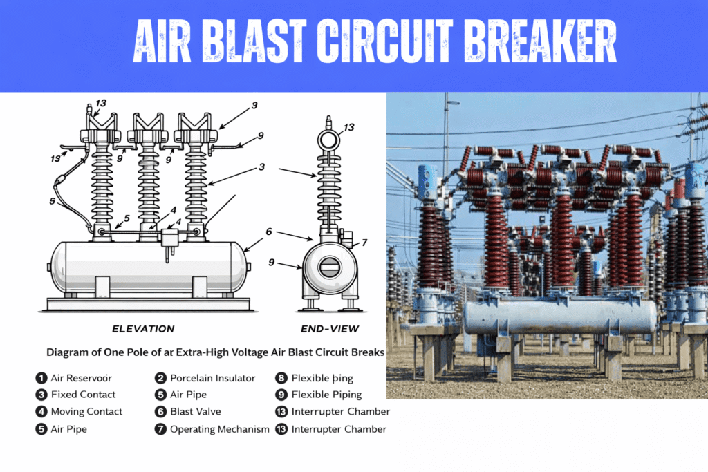
An Air-Blast Circuit Breaker (ABCB) is a high-voltage circuit breaker in which compressed air is used to extinguish the electric arc formed when the contacts separate during a fault.
When a trip signal is given, a jet of high-pressure air is blown across the contact gap. This air rapidly cools and de-ionizes the arc, so the dielectric strength between the contacts rises quickly and the current is interrupted.
Construction of an Air-Blast Circuit Breaker
A typical air-blast circuit breaker consists of the following main components:
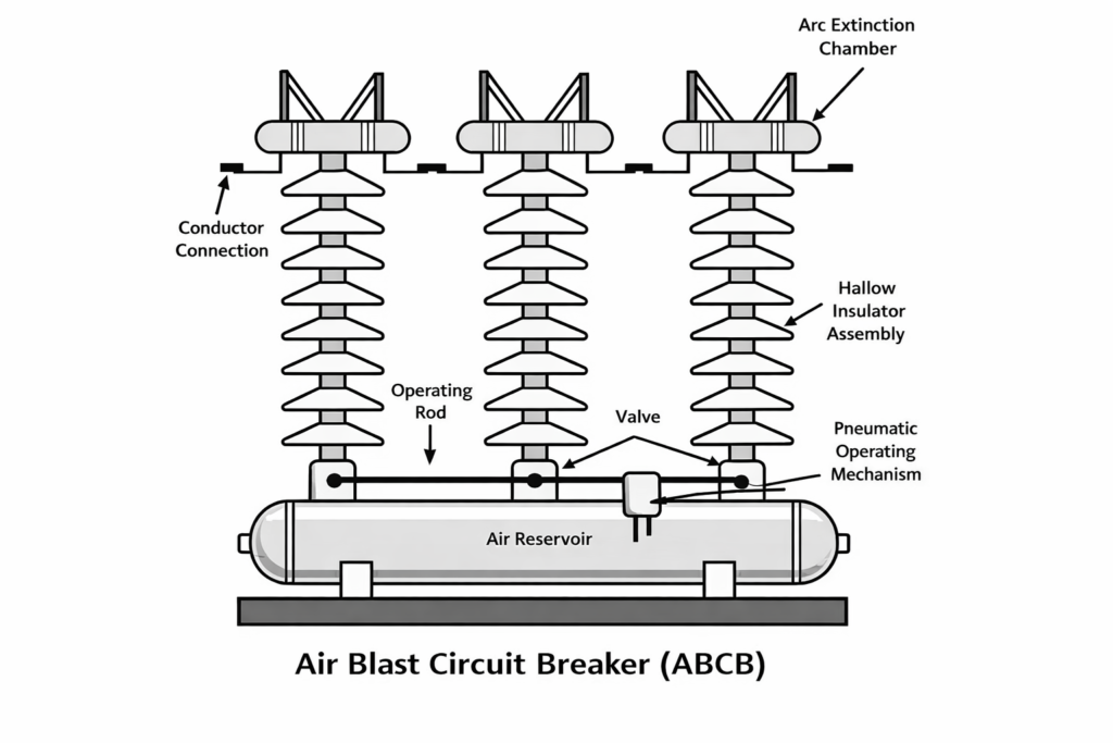
The construction of an air-blast circuit breaker is designed to deliver a controlled jet of high-pressure air to the contact gap so that the arc is rapidly cooled and de-ionized. The main parts are described below.
Air reservoir
A steel tank used to store compressed air (typically about 20–30 bar). It is supplied by an auxiliary compressor plant and provides the energy required for arc extinction and contact operation.
Hollow insulator assembly
Porcelain or composite hollow insulators are mounted on the air reservoir. They form the air passage from the reservoir to the interrupter and also provide the necessary electrical insulation between live parts and the grounded structure.
Arc-extinction (interrupter) chamber
This chamber is mounted at the top of each hollow insulator.
It contains:
- a fixed contact,
- a moving contact, and
- an air-blast nozzle or passages.
All making and breaking of the circuit take place inside this chamber.
Valves (blast/control valves)
Valves are installed at the base of the hollow insulators or in the air supply line. They regulate the flow of compressed air from the reservoir to the interrupter chamber and are operated by the pneumatic operating mechanism during tripping.
Operating mechanism
A pneumatic (or electro-pneumatic) mechanism operates the valves and, in many designs, assists the movement of the contacts. It ensures rapid opening and proper timing of the air blast.
Current-carrying conductors
These conductors connect the interrupter chambers to each other (for multi-break arrangements) and to the external terminals of the circuit breaker.
Operation of Air-Blast Circuit Breaker
Under normal operating conditions, the contacts inside the arc-extinction chamber remain closed and carry the load current. When a fault occurs, the protection system sends a tripping signal to the breaker. This signal operates the pneumatic mechanism, which opens the control valves through an operating rod. As soon as the valves open, high-pressure air from the air reservoir flows through the hollow insulator assembly into the arc-extinction chamber.
The incoming high-pressure air exerts force on the moving contact, causing it to separate from the fixed contact.
At the moment of separation, an electric arc is formed between the contacts due to the ionization of air in the contact gap. The high-velocity air blast rapidly removes the ionized particles and cools the arc path. Consequently, the arc is extinguished and the dielectric strength between the contacts rises quickly.
After a short travel of the moving contact, the outlet passages are closed. This traps compressed air inside the chamber and further increases the dielectric strength, thereby preventing restriking of the arc. Once the fault is cleared and the interruption is completed, the valves are closed and the pressure acting on the moving contact falls to atmospheric value. The spring mechanism then returns the moving contact to its original position, re-establishing the circuit.
Related Posts: Sulphur Hexafluoride (SF₆) Circuit Breaker
Types of Air-Blast Circuit Breakers
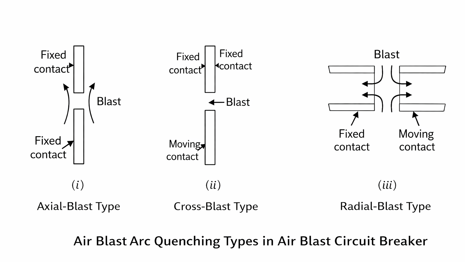
Depending upon the direction of air-blast in relation to the arc, air-blast circuit breakers
are classified into:
- Axial-blast type in which the air-blast is directed along the arc path as shown in
Fig. (i) - Cross-blast type in which the air-blast is directed at right angles to the arc path as
shown in Fig. (ii). - Radial-blast type in which the air-blast is directed radially as shown in Fig. (iii)
Axial-blast Type
Fig: 2 shows the essential components of a typical axial blast air circuit breaker. The fixed and moving contacts are held in the closed position by spring pressure under normal conditions. The air reservoir is connected to the arcing chamber through an air valve. This valve remains closed under normal conditions but opens automatically by the tripping impulse when a fault occurs on the system. When a fault occurs, the tripping impulse causes opening of the air valve which connects the circuit breaker reservoir to the arcing chamber.
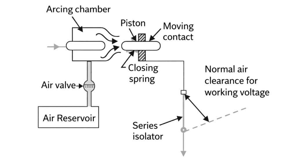
The high pressure air entering the arcing chamber pushes away the moving contact against spring pressure. The moving contact is separated and an arc is struck. At the same time, high pressure air blast flows along the arc and takes away the ionized gases along with it. Consequently, the arc is extinguished and current flow is interrupted.
It may be noted that in such circuit breakers, the contact separation required for interruption is generally small (1.75 cm or so). Such a small gap may constitute inadequate clearance for the normal service voltage. Therefore, an isolating switch is incorporated as a part of this type of circuit breaker. This switch opens immediately after fault interruption to provide the necessary clearance for insulation.
Cross-blast Type
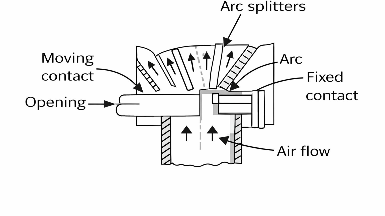
In this type of circuit breaker, an air-blast is directed at right angles to the arc. The cross-blast lengthens and forces the arc into a suitable chute for arc extinction. When the moving contact is withdrawn, an arc is struck between the fixed and moving contacts. The high pressure cross-blast forces the arc into a chute consisting of arc splitters and baffles. The splitters serve to increase the length of the arc and baffles give improved cooling. The result is that arc is extinguished and flow of current is interrupted. Since blast pressure is same for all currents, the inefficiency at low currents is eliminated. The final gap for interruption is great enough to give normal insulation clearance so that a series isolating switch is not necessary.
Radial-blast Type
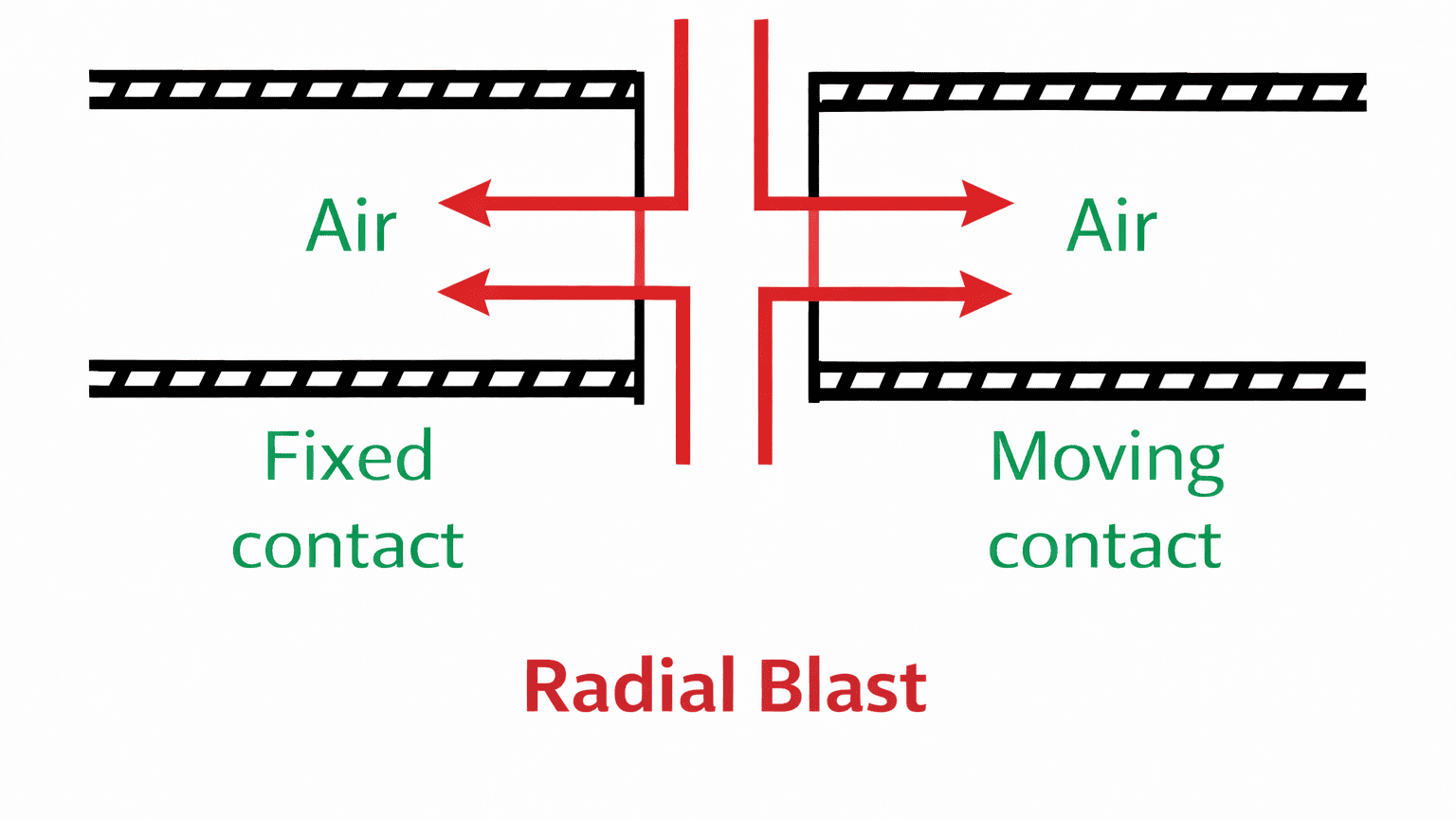
In this type of circuit breaker, the compressed air blast is directed radially outward from the arc region. When the moving contact is withdrawn, an arc is struck between the fixed and moving contacts. The high-pressure air enters the arc zone and flows from the centre towards the periphery, thereby forcing the arc outward into the surrounding passages of the arc-extinction chamber.
This radial flow of air rapidly cools and de-ionizes the arc column and removes the hot ionized gases from the contact region. Due to the strong and uniform outward air flow, the arc is constricted and its length is increased, which results in a rapid rise of the dielectric strength of the contact gap.
Consequently, the arc is extinguished at the next current zero and the flow of current is interrupted. Since the air pressure used for arc extinction is substantially independent of the magnitude of the current, satisfactory performance is obtained over a wide range of fault currents. After interruption, the contact separation is sufficient to provide the normal insulation clearance, and therefore a separate series isolating switch is generally not required.
Advantages
- Very fast arc extinction due to strong radial air flow.
- Efficient removal of ionized gases from the arc region.
- High dielectric recovery after current zero.
- Uniform air flow around the arc gives good cooling performance.
- Suitable for high interrupting capacity.
Disadvantages
- Construction of the radial flow chamber is comparatively complex.
- Requires a compressed-air system (compressor, reservoir, valves, piping).
- Higher maintenance than modern circuit breakers.
- Occupies more space than SF₆ and vacuum circuit breakers.
- Now considered obsolete in most new installations.
Applications
Radial-blast air circuit breakers were mainly used in:
- High-voltage and extra-high-voltage substations
- Transmission line protection
- Generator and transformer protection
- Installations where very fast arc extinction and rapid dielectric recovery were required.
Today, radial-blast (and other air-blast) circuit breakers are largely replaced by SF₆ and vacuum circuit breakers.