Introduction
Insulation classes in electric motors define the maximum permissible operating temperature of the motor’s internal insulation system and directly determine its reliability, lifetime, and safe loading capability. For engineers, selecting the correct insulation class is not only a compliance requirement but also a critical design decision that affects thermal margin, overload capability, efficiency, and maintenance cost.
In practical machines, the insulation system must withstand electrical stress, mechanical vibration, moisture, contamination, and continuous thermal cycling. Internationally accepted guidelines issued by organizations such as International Electrotechnical Commission (IEC) and Institute of Electrical and Electronics Engineers (IEEE) standardize how insulation temperature limits are defined and tested.
This article explains the concept of insulation classes, temperature limits, thermal design considerations, and their real impact on motor construction and performance specifically for engineering students and practicing electrical engineers.
What are Insulation Classes in Motors?
An insulation class specifies the maximum allowable temperature at which the motor’s insulation system can operate safely without excessive degradation.
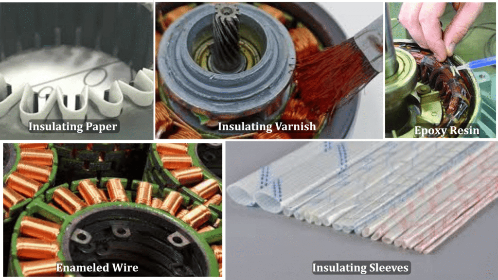
In an electric motor, insulation is used in:
- Stator winding conductors
- Slot liners and wedges
- Inter-turn and inter-phase insulation
- End-winding supports and tapes
The insulation class is assigned to the entire insulation system, not to a single material.
Design and Selection of Insulation Class in Motors
Selection of insulation class is a thermal design decision, not merely a catalog choice.
Standard Insulation Classes and Temperature Limits
According to commonly used IEC and IEEE practices, motor insulation systems are classified as follows.
| Insulation class | Maximum temperature limit (°C) | Typical insulating material examples used in motors |
|---|---|---|
| Class A | 105 °C | • Cotton / silk insulation impregnated with varnish • Cellulose paper (pressboard, kraft paper) • Oil-impregnated paper systems |
| Class E | 120 °C | • Improved synthetic varnishes • Polyester based enamelled wire coatings • Upgraded paper–varnish composite systems |
| Class B | 130 °C | • Mica paper with epoxy or polyester resin • Glass-fibre reinforced tapes with varnish • Polyimide-modified enamelled copper wire |
| Class F | 155 °C | • Mica–glass tapes with epoxy resin • Glass fibre slot liners with resin bonding • Polyimide or polyester-imide magnet wire enamel |
| Class H | 180 °C | • Silicone rubber insulation • Silicone resin impregnated glass fibre • High-temperature polyimide films and tapes |
Practical interpretation for motor construction
- Class A / E
- Mostly found in older machines and low-temperature applications
- Limited thermal margin
- Class B
- Traditional industrial standard
- Widely used in general-purpose induction motors
- Class F
- Most common insulation system in modern industrial motors and inverter-fed drives
- Class H
- traction motors
- servo motors
- aerospace and high-power-density machines
- severe ambient and duty conditions
Temperature Rise, Hot-Spot and Thermal Margin
In practical motor thermal analysis, the winding hot-spot temperature is calculated using the standard thermal relation:
Where:
- Tw = winding hot-spot temperature (°C)
- Ta = ambient temperature around the motor (°C)
- ΔT = average temperature rise of the winding above ambient (°C)
- Ths = hot-spot allowance (°C)
Key definitions
- Temperature rise (ΔT)
The increase in the average winding temperature above the surrounding ambient temperature. - Hot spot (Ths)
The local maximum temperature occurring at the most thermally stressed part of the winding (typically deep inside the stator slot or end-turn bundle). - Thermal margin
The safety difference between the insulation class temperature limit and the actual winding hot-spot temperature:
Where:
- Tclass = permissible temperature of the selected insulation class (°C)
- Tw = calculated winding hot-spot temperature (°C)
The hot-spot temperature determines the true thermal stress on the insulation system, not the average winding temperature. A motor can meet its rated temperature rise limit but still suffer insulation aging if the hot-spot allowance is underestimated.
Maintaining a positive thermal margin is essential for:
- long insulation life,
- overload capability,
- and safe inverter-fed operation.
Effect of insulation class on motor life
Motor insulation life is mainly controlled by winding hot-spot temperature. Insulation aging follows an Arrhenius-type behavior, and in practice a 10 °C increase in operating temperature roughly halves the insulation life. The insulation class only specifies the maximum allowable temperature, not the expected lifetime. Longer motor life is achieved when a higher insulation class is used but the motor is operated at a lower temperature rise, which provides a higher thermal margin and better reliability.
Practical design rule
If a motor is:
- Designed with Class F insulation (155 °C)
- but operated such that the winding temperature remains near Class B level (130 °C),
then the insulation system typically exhibits a much longer useful life, even under inverter-fed and variable-load operation