
Introduction
The Sumpner’s test, commonly known as back-to-back test, is used to determine the iron loss, full-load copper loss, efficiency and temperature rise of a transformer under actual operating conditions, without connecting any external load.
The commonly used open-circuit (O.C.) and short-circuit (S.C.) tests are mainly performed to obtain the equivalent-circuit parameters of a transformer. Although these two tests give iron loss and copper loss separately, they cannot provide heating information. In real operation, a transformer experiences both losses simultaneously. Hence, O.C. and S.C. tests do not represent true loading conditions.To overcome this limitation, Sumpner’s test is used.
Circuit Diagram
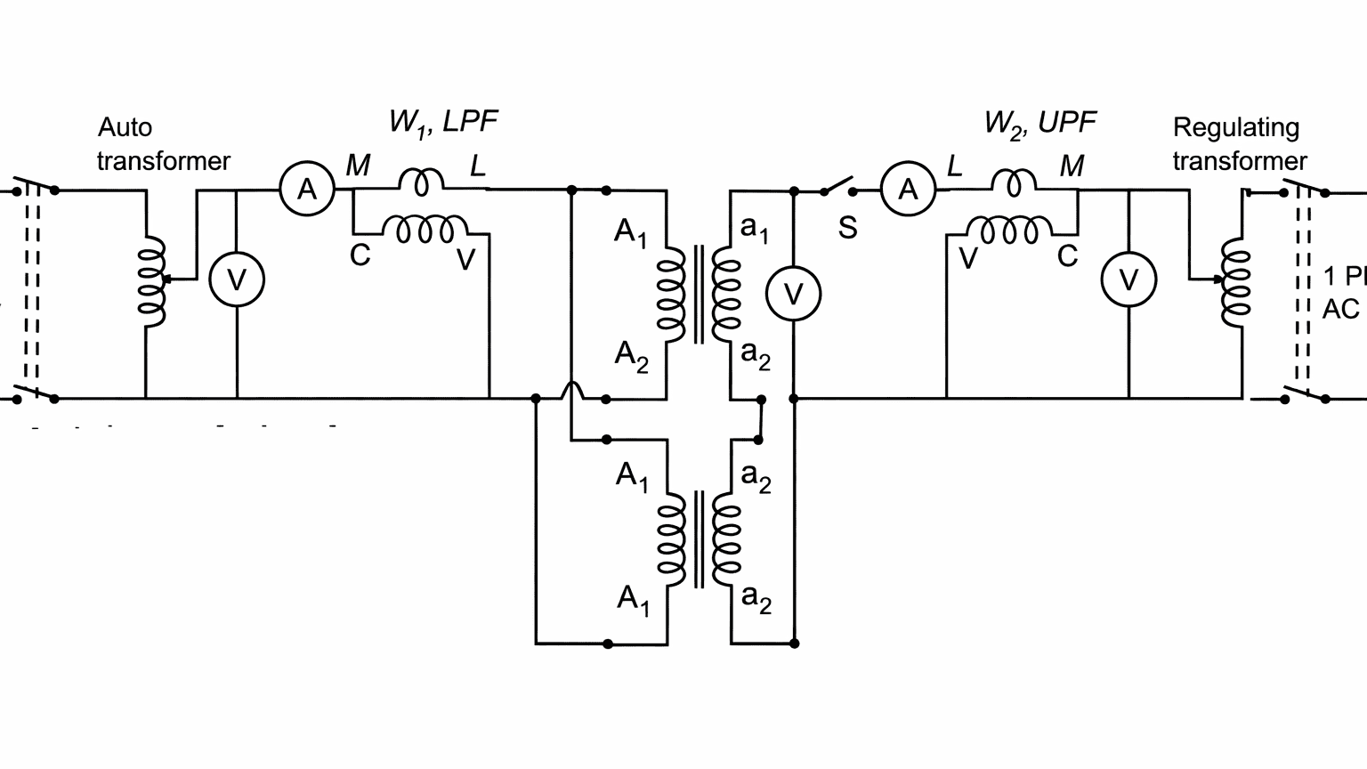
Sumpner’s test, also called the back-to-back test, can be performed only when two identical transformers are available. In this method, both transformers are connected to the supply in such a way that one transformer is effectively loaded by the other. The primaries of the two identical single-phase transformers are connected in parallel across the supply. The secondary windings are connected in series opposition, so that their induced e.m.f.s oppose each other.
A separate low-voltage adjustable supply (through a regulating transformer) is connected in series with the secondary circuit to circulate the required current and obtain the readings, as shown in the circuit diagram.
Step 1 – No-load condition (iron loss measurement)
- Rated voltage is applied to both primaries.
- Since the secondaries are in opposition, no circulating current flows.
- Each transformer operates under no-load condition.
The current drawn from the supply is:
where is the no-load current of one transformer.
The wattmeter W₁ measures the total iron loss of both transformers.
where
= iron loss of one transformer.
Step 2 – Full-load condition (copper loss measurement)
A small voltage is injected into the secondary loop using the regulating transformer.
The injected voltage is adjusted until the rated secondary current flows.
Under this condition:
- both secondary windings carry rated current, and
- by transformer action, both primary windings also carry rated current.
Thus, the transformers operate under true full-load condition.
The wattmeter W₂ measures the total full-load copper loss of both transformers.
where
= full-load copper loss of one transformer.
Determination of efficiency
If the rated output of one transformer is , then
where
- = iron loss per transformer
- = full-load copper loss per transformer
Determination of temperature rise
Since both transformers operate with:
- rated voltage applied to the primaries, and
- rated current flowing in all windings,
the heating conditions are the same as in actual service.
By running the test for a sufficient time and observing oil or winding temperature, the temperature rise of the transformer is obtained.
This makes the test economical and safe.
Advantages of Sumpner’s test
- Full-load test is performed without external load.
- Both iron loss and full-load copper loss are obtained accurately.
- Temperature rise can be directly observed.
- Only loss power is drawn from the supply.
- Very suitable for large transformers.
Limitations
- Two transformers of identical rating and characteristics are required.
- The test cannot be carried out on a single transformer alone.
- Additional regulating equipment is required.
Related Posts:
Open Circuit and Short Circuit Test on Transformer
Polarity Test of a Transformer